# AndyMark Docs
Welcome to AndyMark Docs: your central destination for knowledge, inspiration, and practical guidance in FIRST Robotics.
Built by AndyMark, this resource hub brings together trusted documentation, practical guides, and real-world examples drawn from years of hands-on experience in competitive and educational robotics. Whether you're learning the basics or refining advanced systems, you'll find the tools, insights, and proven approaches you need to design, build, and iterate with confidence.
***
### Other Resources
*
*
*
# How Do I... FTC?
The How Do I…? series for FIRST Tech Challenge provides quick, practical answers to common FTC build, design, and troubleshooting questions.
### How Do I... Play Biobuzz with Robits?
### How Do I... Build with Robits?
Cover image
How Do I Play DECODE Using the Robits Starter Bot?
The Robits Starter Bot is built entirely from our Robits Core Kit and has assembly instructions on our website. Use this for playing the game competitively, or simply as a learning exercise!
The combination of AndyMark's Performance Wheels and Grey Grippy Tread creates a solid base with an easily replaceable tread that can be used for seasons to come.
# How Do I... FRC?
The How Do I…? series for FIRST Robotics Competition delivers concise, hands‑on tips for tackling FRC design, integration, and troubleshooting challenges throughout the build season.
### How Do I... Design for Rebuilt?
Cover image
How Do I Score FUEL in REBUILT™?
Launchers used with a round game piece are very common in FRC. Let us walk you through the challenges that come with launchers and the solutions that teams have found over the years.
REBUILT™ is a game unlike we've ever seen before... Or very similar to what we've seen... Very similar indeed. Our engineers bring that past experience to analyze this game!
How Do I Score Using an Elevator or Arm in Reefscape?
Being able to extend is a fundamental part of this year's game, Reefscape. There are a few tried and true methods to do this, and we're here to walk you through them!
Robot Inspection can be an intimidating process when walking into it for the first time. In this video, Jonathan, AM engineer and Volunteer Robot Inspector, walks through what to expect and how to prepare for Inspection.
How Do I Prepare a Driver Station for Competition?
The driver station, or operator console, or whatever your team calls it, is imperative to matchplay. Being able to control your robot and stay connected can make or break a match.
# How Do I... General?
AndyMark staff walk you through guidance on key tools, sound build practices, and practical techniques to help teams work smarter and make better design and build decisions.
### How Do I... Use tools around the shop?
chain
solder
set screw
### How Do I... Use common materials?
finish
tap churro
use polybelt
### How Do I... Best practices?
manage wires
pick a durometer
grease a gearbox
# CAN Device Firmware
# AM\_ColorSensor
### AM\_ColorSensor
#### 3.0.0
[Download](https://andymarkproductsoftware.github.io/amlib-vendordep/Device_Firmware/AM_CAN_ColorSensor/AM_CAN_ColorSensor3.0.0.bin)
* Revamped Firmware update to be more robust
#### 2.2.1
[Download](https://andymarkproductsoftware.github.io/amlib-vendordep/Device_Firmware/AM_CAN_ColorSensor/AM_CAN_ColorSensor2.2.1.bin)
* Improved updating firmware using AndyMark CAN Utility
#### 2.1.0
[Download](https://andymarkproductsoftware.github.io/amlib-vendordep/Device_Firmware/AM_CAN_ColorSensor/AM_CAN_ColorSensor2.1.0.bin)
* Fixed logic for recovering from CAN bus error that can occasionally show up in normal use
#### 1.1.2
* Fixed issue where default report period was 0ms, spamming the CAN bus
[Download](https://andymarkproductsoftware.github.io/amlib-vendordep/Device_Firmware/AM_CAN_ColorSensor/AM_CAN_ColorSensor1.1.2.bin)
#### 1.1.1
* Added ability to turn on board LED on or off for better data
[Download](https://andymarkproductsoftware.github.io/amlib-vendordep/Device_Firmware/AM_CAN_ColorSensor/AM_CAN_ColorSensor1.1.1.bin)
# AM\_HexBoreEncoder
### AM\_HexBoreEncoder
#### 3.0.0
[Download](https://andymarkproductsoftware.github.io/amlib-vendordep/Device_Firmware/AM_CAN_HexBoreEncoder/AM_CAN_HexBoreEncoder3.0.0.bin)
* Revamped Firmware update to be more robust
#### 2.2.1
[Download](https://andymarkproductsoftware.github.io/amlib-vendordep/Device_Firmware/AM_CAN_HexBoreEncoder/AM_CAN_HexBoreEncoder2.2.1.bin)
* Improved updating firmware using AndyMark CAN Utility
#### 2.1.0
[Download](https://andymarkproductsoftware.github.io/amlib-vendordep/Device_Firmware/AM_CAN_HexBoreEncoder/AM_CAN_HexBoreEncoder2.1.0.bin)
* Fixed logic for recovering from CAN bus error that can occasionally show up in normal use
#### 1.1.1
* Fixed issue where default report period was 0ms, spamming the CAN bus
[Download](https://andymarkproductsoftware.github.io/amlib-vendordep/Device_Firmware/AM_CAN_HexBoreEncoder/AM_CAN_HexBoreEncoder1.1.1.bin)
#### 1.1.0
* LED now flashes on power on
[Download](https://andymarkproductsoftware.github.io/amlib-vendordep/Device_Firmware/AM_CAN_HexBoreEncoder/AM_CAN_HexBoreEncoder1.1.0.bin)
# AM\_MagSwitch
#### 3.0.0
[Download](https://andymarkproductsoftware.github.io/amlib-vendordep/Device_Firmware/AM_CAN_MagSwitch/AM_CAN_MagSwitch3.0.0.bin)
* Revamped Firmware update to be more robust
#### 2.2.1
[Download](https://andymarkproductsoftware.github.io/amlib-vendordep/Device_Firmware/AM_CAN_MagSwitch/AM_CAN_MagSwitch2.2.1.bin)
* Improved updating firmware using AndyMark CAN Utility
#### 2.1.0
[Download](https://andymarkproductsoftware.github.io/amlib-vendordep/Device_Firmware/AM_CAN_MagSwitch/AM_CAN_MagSwitch2.1.0.bin)
* Fixed logic for recovering from CAN bus error that can occasionally show up in normal use
# AM\_CAN\_Koors40
#### 3.0.1
[Download](https://andymarkproductsoftware.github.io/amlib-vendordep/Device_Firmware/AM_CAN_Koors40/AM_CAN_Koors40_3.0.1.bin)
*
# AM\_Lidar
#### 3.0.0
[Download](https://andymarkproductsoftware.github.io/amlib-vendordep/Device_Firmware/AM_CAN_Lidar/AM_CAN_Lidar3.0.0.bin)
* Revamped Firmware update to be more robust
#### 2.2.1
[Download](https://andymarkproductsoftware.github.io/amlib-vendordep/Device_Firmware/AM_CAN_Lidar/AM_CAN_Lidar2.2.1.bin)
* Improved updating firmware using AndyMark CAN Utility
#### 2.1.0
[Download](https://andymarkproductsoftware.github.io/amlib-vendordep/Device_Firmware/AM_CAN_Lidar/AM_CAN_Lidar2.1.0.bin)
* Fixed logic for recovering from CAN bus error that can occasionally show up in normal use
# CAN Device Configuration
# AndyMark IPK for SystemCore
The AndyMark IPK is designed to allow teams to set up CAN devices and do simple diagnostics through a web browser while connected to the SystemCore
The AndyMark IPK will show you all AndyMark CAN devices connected to the SystemCore. The device cards show an overview for the device. Click on a device card to get more info and config options
You can set the CAN ID and name of the device by typing into the appropriate boxes and hitting enter or the button to the right of the box\
\
\
\
\
If you scroll down, you can get live data or motor control for your device and also access the Update Firmware function.
### Make sure to read all prompts when going through the update process
If your AndyMark CAN device is not running firmware 3.0.0 or newer, go [here](/frc-electronics/can-device-configuration/andymark-ipk-for-systemcore/legacy-update-device-firmware) to learn how to properly update firmware to 3.0.0 or newer for a faster, more robust firmware update process
# Download
## [Releases](https://github.com/AndyMarkProductSoftware/amlib-vendordep/releases)
# Installation Instructions
### 1. Navigate to "[http://robot.local/" in your web browser](http://robot.local/)
### 2. Go to "" and download the most recent version of the AndyMark IPK
### 3. Click on "Add Package" and drag the downoaded IPK onto the screen
### 4. Wait until the package installs successfully
### 5. The AndyMark IPK is now installed. Click on the card with the AndyMark logo to open the IPK
### To uninstall, hover over the card and click the trash icon
# Legacy Update Device Firmware
If your AndyMark CAN device running firmware less than 3.0.0 uses an older update process that is more fragile on SytemCore. \
\
The AndyMark IPK knows then a device is running firmware that uses the Legacy update process and will give instructions.\
\
To have the best chances of success, ensure the device you are updating are on a relatively quiet bus. This means unplugging or powering off all other devices on the bus. Once updated to any firmware 3.0.0 or higher, this will not be necessary.\
\
If the update fails, power cycle both the device and the SystemCore
# AndyMark CAN Interface Utility
## **FOR ROBORIO/WPILIB VERSIONS 2026 OR OLDER. FOR SYSTEMCORE AND 2027 SEASON OR LATER, USE ANDYMARK IPK FOR SYSTEMCORE**
[Link to Downloads Page](/frc-electronics/can-device-configuration/andymark-can-interface-utility/andymark-can-utility-installer)
{% stepper %}
{% step %}
### Run the server
The first step to using the AndyMark CAN Utility is to run a server that is included with the AndyMark WPILib Vendor Library. By initializing any AndyMark CAN devices in a WPILib robot project, the server will be running when your computer is connected to the RoboRIO and that robot code is running.
{% endstep %}
{% step %}
### Connect to the RoboRIO
Enter the team number of the RoboRIO in the team number box.
Click the "ConnectToRio" button to connect to the server running on the RoboRIO. Any AndyMark CAN devices will then appear in the table.
{% endstep %}
{% step %}
### Interact with devices
To interact with devices, click on the device in the table. It will highlight the row of the device. By double clicking on the device's CAN ID or device name, entering the number or name you want, then hitting enter (CAN IDs are limited to 0-63. Device name can include any character, but is limited to 7 characters)
By clicking the buttons with a device selected, you can interact further with the devices.
* "Identify Device" will cause the device to blink its LEDs so you can find the device.
* "Restart Device" will send a signal to the device telling it to restart
* "Start Reprogram" will prompt the user to select a firmware file and initiate the reprogram process

Note on reprogramming
If you are using device firmware less than 2.2.1 and the WPILib AndyMark vendor dep less than 2026.1.0, updating the firmware using the CAN utility will spike CAN utilization to around 80%. Because of this, reprogramming can take a long time if there are other CAN devices on the bus. Best practice is to update device firmware and AndyMark Vendordep. If you are updating device firmware less than 2.2.1, you should pull breakers for all other devices or just make sure the device you wish to update is the only one on the CAN bus to avoid a very long update process. Once the update is complete and the device is on version 2.2.1 or newer, this will not be necessary
Firmware update progress will be printed into the Driver Station's console
Ensure that you are choosing firmware for the correct device. Uploading firmware for the wrong device will likely render your CAN device inoperable
{% endstep %}
{% step %}
### Server Setup
The RoboRIO code status message and "Server Setup" tab (4.) is an experimental feature to install the server on the RoboRIO without a WPILib project with the AndyMark VendorDep installed.
If you must use this, make sure some robot code is running on the RobRIO. Then, click "Set Up Server on RIO" button under the "Server Setup" button. This is destructive to Robot Code and the RIO will not run any Robot Code until "Restore Robot Code" is clicked. This will cause the RIO to be able to run Robot Code again and then will reboot.
If there is a failure during this process, you may have to reupload robot code before clicking "Restore Robot Code". You may also have to reformat the RoboRIO
{% endstep %}
{% endstepper %}
# AndyMark CAN Utility Installer
## Latest
[AndyMarkCANUtilityLatestInstall.zip](https://andymarkproductsoftware.github.io/amlib-vendordep/CAN_Utility/AndyMarkCANUtilityLatestInstall.zip)
## 1.1.0
* More AndyMark CAN devices show actual names instead of "Unknown AndyMark Device"
[AndyMarkCANUtility1.1.0.zip](https://andymarkproductsoftware.github.io/amlib-vendordep/CAN_Utility/AndyMarkCANUtility1.0.2.zip)
## 1.0.2
* Original Release
[AndyMarkCANUtility1.0.2.zip](https://andymarkproductsoftware.github.io/amlib-vendordep/CAN_Utility/AndyMarkCANUtility1.0.2.zip)
# WPILib AM Vendor Library Setup
To install the AndyMark WPILib dependencies, click the WPILib tab on the right side of the VSCode window. Then, find the AndyMark AM Library and click install. This will install all of the libraries needed for AndyMark CAN devices.

#### Alternative: To install using vendor JSON
{% stepper %}
{% step %}
### Click the "Open WPILib Command Palette" button in VS Code

{% endstep %}
{% step %}
### In the text box, begin typing "Manage Vendor Libraries" and click on the command

{% endstep %}
{% step %}
### Click on "Install new libraries (online)"

{% endstep %}
{% step %}
### Paste the link to the most recent vendor JSON for the WPILib year
Links to the AndyMark vendor JSONs can be found [here](/frc-electronics/wpilib-am-vendor-library-setup/andymark-vendor-jsons).
### Hit enter
WPILib will fetch the appropriate files for you to start writing code for AndyMark CAN devices.
{% endstep %}
{% endstepper %}
# AndyMark Vendor JSONs
## 2027\_alpha5
### 2027.0.1-alpha5
## **2026**
### **Latest (2026.1.0):**
Revamped functionality for updating device firmware using the AndyMark CAN utility
### 2026.1.0
Revamped functionality for updating device firmware using the AndyMark CAN utility
### 2026.0.4
Added support for AM CAN Lidar
### 2026.0.3
Added support for AM CAN Magnetic Switch
### 2026.0.2
Added ability to turn LED off and on for the AM CAN Color Sensor
### 2026.0.1
# CAN Sensors
AndyMark CAN Sensors provide compact, locking-connector options for distance, position, color, proximity, and noncontact state detection on FRC robots. Each product page includes specifications, installation guidance, examples, and API resources.
## Products
| Device | Primary measurement |
| ---------------------------------------------------------------------------------------------------------------------- | ------------------------------------------------------------------------------- |
| [CAN Lidar (am-5684)](/frc-electronics/can-sensors/can-lidar-am-5684) | Time-of-Flight distance, measurement status, signal strength, and ambient light |
| [CAN Magnetic Switch (am-5788)](/frc-electronics/can-sensors/can-magnetic-switch-am-5746) | Noncontact magnet detection |
| [CAN Hex Bore Absolute Encoder (am-5200\_can)](/frc-electronics/can-sensors/can-hex-bore-absolute-encoder-am-5200_can) | Absolute shaft position, plus velocity over CAN |
| [CAN Color Sensor (am-5683)](/frc-electronics/can-sensors/can-color-sensor-am-5683) | RGB/clear color data and proximity |
## Common bring-up workflow
1. Disconnect robot power before wiring or mounting a sensor.
2. Confirm the power, CAN High, and CAN Low connections against the wiring diagram on the device’s Specifications page.
3. Verify that the CAN bus is terminated correctly and that CAN High and CAN Low are not reversed.
4. Install the [AndyMark WPILib vendor library](/frc-electronics/wpilib-am-vendor-library-setup).
5. If multiple new AndyMark CAN devices use CAN ID 0, connect and configure them one at a time so each receives a unique ID before they share the bus.
6. For roboRIO/WPILib 2026 or earlier, use the [AndyMark CAN Interface Utility](/frc-electronics/can-device-configuration/andymark-can-interface-utility). For SystemCore and the 2027 season or later, use the [AndyMark IPK for SystemCore](/frc-electronics/can-device-configuration/andymark-ipk-for-systemcore).
7. Confirm that the device is discovered before troubleshooting application code.
## Installation practices
* Mount each sensor rigidly and protect it from impacts, water, conductive debris, and metal chips.
* Keep CAN wiring as a continuous bus rather than creating long unterminated branches.
* Route and support cables with appropriate strain relief so vibration, impacts, or service work cannot load the connector or pull conductors loose.
* Record each device name, CAN ID, location, and firmware version.
* Validate readings on the actual robot, using the real target materials, lighting, motion, and electrical environment.
{% hint style="warning" %}
A device appearing in software does not by itself prove that its measurements are valid. Check device status, wiring, mounting, configuration, and live sensor data before using a reading for closed-loop control.
{% endhint %}
# CAN Lidar (am-5684)

The **AndyMark CAN Lidar** is a compact Time-of-Flight distance sensor that reports distance, measurement status, signal strength, and ambient-light data over CAN. The CAN version uses a VL53L1X sensing IC and is intended for presence detection, positioning, and distance-based robot actions.
See Specifications for electrical and mechanical limits, Examples for code, Validation for reading-quality checks, and Tuning for configuration guidance.
***
## At a glance
| Parameter | Value |
| --------------------------- | ------------------------------ |
| AndyMark part number | am-5684 |
| Communication | CAN |
| Sensing technology | VL53L1X Time-of-Flight |
| Published measurement range | Approximately 30 mm to 4000 mm |
| Field of view | Approximately 25° |
| Default CAN ID | 0 |
| Maximum input voltage | 16 V |
## When to use this sensor
* Detect a game piece entering an intake or feeder.
* Stop or align a mechanism at a measured distance.
* Maintain spacing from a wall or field element.
* Monitor distance changes while validating a mechanism.
* Use signal and ambient data to reject low-quality measurements.
## Before installation
* Choose a rigid mounting location with an unobstructed view of the target.
* Keep the sensing face protected from impacts, contamination, and direct contact.
* Test the actual target surface; dark, reflective, small, or angled targets may reduce usable range.
* Provide cable support and strain relief near the sensor.
* Configure a unique CAN ID before installing multiple devices that ship with the same default ID.
## Initial checks
1. Verify CAN discovery and the configured device ID.
2. Confirm that the reported distance changes in the expected direction as the target moves.
3. Review the status code before accepting a measurement.
4. Compare signal strength with ambient light under realistic conditions.
5. Validate readings at the exact distances and target angles the robot will use.
## Resources
* [CAN Lidar product page](https://andymark.com/products/lidar-distance-sensor-andymark-standard-sensors?variant=46151725088940)
* Examples
* Device API
# Specifications
## Electrical and sensing
| Parameter | Published value |
| --------------------- | ------------------------------------------------ |
| AndyMark part number | am-5684 |
| Communication | CAN |
| Default CAN ID | 0 |
| Nominal voltage | 3.3 V |
| Maximum input voltage | 16 V |
| Sensing IC | VL53L1X |
| Measurement channels | Distance, status, peak signal, and ambient light |
| Minimum range | Approximately 30 mm |
| Maximum range | Approximately 4000 mm |
| Field of view | Approximately 25° |
{% hint style="info" %}
Maximum usable range depends on target size, color, reflectivity, angle, ambient light, timing budget, and other tuning settings.
{% endhint %}
## Mechanical
| Parameter | Published value |
| -------------- | ---------------------------- |
| Dimensions | 2.00 in × 0.745 in × 0.51 in |
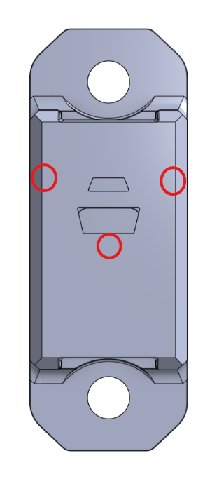
| Mounting holes | #10 holes, 1.5 in apart |
| Connector | JST-PA, BM04B-PASS-1-TFT |
### Mechanical drawing
Verify the physical product before finalizing a mounting design.
## Wiring

## Product resource
[CAN Lidar product page](https://andymark.com/products/lidar-distance-sensor-andymark-standard-sensors?variant=46151725088940)
# Examples
## Use case
This example reads the CAN Lidar’s distance, status, flags, peak signal, and ambient-light values and publishes them to SmartDashboard. Use it to verify CAN communication, confirm the configured device ID, evaluate mounting, and collect data for application-specific validation thresholds.
{% hint style="info" %}
The snippets use CAN bus 2 and device ID 0. Change both values to match the controller and sensor configuration.
{% endhint %}
## Mounting example
Mount the sensor rigidly with an unobstructed view of the target.
## Setup
Install the [AndyMark WPILib vendor library](/frc-electronics/wpilib-am-vendor-library-setup) before using these examples. See [Device API](/frc-electronics/can-sensors/can-lidar-am-5684/device-api) for all available methods.
{% tabs %}
{% tab title="Java" %}
```java
import com.andymark.jni.AM_CAN_Lidar;
import com.andymark.jni.AM_CAN_Lidar.AM_LidarData;
import com.andymark.jni.AM_CAN_Lidar.AM_LidarDebugData;
import edu.wpi.first.wpilibj.smartdashboard.SmartDashboard;
// CAN bus 2, device ID 0
AM_CAN_Lidar myLidar = new AM_CAN_Lidar(2, 0);
// Restore the default 50 ms report period.
myLidar.resetReportPeriod();
AM_LidarData data = myLidar.getData();
AM_LidarDebugData debug = myLidar.getDebugData();
SmartDashboard.putNumber("Lidar/DistanceMm", data.distanceMm);
SmartDashboard.putNumber("Lidar/Status", data.status);
SmartDashboard.putNumber("Lidar/Flags", data.flags);
SmartDashboard.putNumber("Lidar/TimestampMs", data.millisStamp);
SmartDashboard.putNumber(
"LidarDebug/PeakSignalCentiMcps",
debug.peakSignalCentiMcps
);
SmartDashboard.putNumber(
"LidarDebug/AmbientCentiMcps",
debug.ambientCentiMcps
);
SmartDashboard.putNumber(
"LidarDebug/TimestampMs",
debug.millisStamp
);
```
{% endtab %}
{% tab title="C++" %}
```cpp
#include "AM_CAN_Lidar.h"
#include
// CAN bus 2, device ID 0
AM_CANLidar myLidar{2, 0};
// Restore the default 50 ms report period.
myLidar.ResetReportPeriod();
AM_LidarData data = myLidar.GetData();
AM_LidarDebugData debug = myLidar.GetDebugData();
frc::SmartDashboard::PutNumber("Lidar/DistanceMm", data.distanceMm);
frc::SmartDashboard::PutNumber("Lidar/Status", data.status);
frc::SmartDashboard::PutNumber("Lidar/Flags", data.flags);
frc::SmartDashboard::PutNumber("Lidar/TimestampMs", data.millisStamp);
frc::SmartDashboard::PutNumber(
"LidarDebug/PeakSignalCentiMcps",
debug.peakSignalCentiMcps
);
frc::SmartDashboard::PutNumber(
"LidarDebug/AmbientCentiMcps",
debug.ambientCentiMcps
);
frc::SmartDashboard::PutNumber(
"LidarDebug/TimestampMs",
debug.millisStamp
);
```
{% endtab %}
{% endtabs %}
## Next steps
* Move the target through the full operating range.
* Compare status, peak signal, and ambient values under realistic lighting.
* Use the [Validation](/frc-electronics/can-sensors/can-lidar-am-5684/validation) page to establish acceptance criteria.
* Apply tuning only after recording baseline performance.
# Validation
How to decide whether a CAN Lidar reading is suitable for robot logic
The CAN Lidar reports more than distance. Check status, signal strength, ambient light, timestamps, and application history before using a measurement for autonomous or closed-loop decisions.
{% hint style="warning" %}
The numerical thresholds below are starting points for characterization, not guaranteed acceptance limits. Establish final thresholds with the real target, distance, angle, lighting, timing budget, and mounting.
{% endhint %}
## Data available
Each measurement includes:
* Distance in millimeters
* Status code
* Flags
* Measurement timestamp
* Peak signal in centi-MCPS
* Ambient light in centi-MCPS
* Debug-data timestamp
## 1. Check communication and freshness
Before evaluating distance:
* Confirm the expected device is present at the configured CAN ID.
* Confirm timestamps continue to advance.
* Treat repeated, stale, or timed-out data as invalid.
* Verify that the main and debug data correspond closely enough in time for the application.
## 2. Check the status code
| Status | Meaning | Recommended treatment |
| ------ | --------------- | --------------------------------------------- |
| 0 | Range valid | Continue validation |
| 1 | Sigma fail | Reject |
| 2 | Signal fail | Reject |
| 4 | Phase fail | Reject |
| 5 | Hardware fail | Reject and investigate |
| 7 | Wrap target | Use only with application-specific validation |
| 8 | Processing fail | Reject |
Status 0 is preferred. Status 7 indicates a weak or near-limit condition and should not be treated as equally trustworthy without testing.
## 3. Evaluate peak signal
Peak signal describes the returned optical signal. Higher values generally indicate a stronger return.
A useful initial characterization band is:
| Peak signal | Starting interpretation |
| --------------------------- | ----------------------- |
| Greater than 300 centi-MCPS | Strong |
| 150–300 centi-MCPS | Moderate |
| Less than 150 centi-MCPS | Weak |
Do not use these bands as universal limits. Record how the value changes with the actual target and range.
## 4. Evaluate ambient light
Higher ambient values indicate more background optical energy and can reduce margin, especially at longer distances. A value below 100 centi-MCPS can be used as an initial low-ambient reference, but acceptable values depend on the target and configuration.
## 5. Compare signal with ambient
When the ambient value is greater than zero, calculate:
```
signal-to-ambient ratio = peak signal / ambient
```
Values above 1.5 can be used as an initial characterization target, while values above 2.0 provide more margin. If ambient is zero, do not divide; evaluate status and peak signal directly.
## 6. Apply application checks
A robot should also confirm that:
* Distance is inside the mechanism’s physically possible range.
* The change from the previous accepted sample is plausible.
* Enough consecutive samples agree for the risk of the action.
* A rejected or missing reading produces a safe fallback behavior.
## Example acceptance policy
A conservative starting policy might require:
* Fresh data
* Status 0
* Peak signal greater than an experimentally selected threshold
* Adequate signal-to-ambient ratio
* Two or more consecutive plausible samples
Status 7 may be handled separately when the application can tolerate reduced confidence.
## Validation procedure
1. Collect data across the full operating distance.
2. Repeat for each target material, angle, and lighting condition.
3. Record both successful readings and failure modes.
4. Select thresholds with margin between valid and invalid cases.
5. Recheck after changing the sensor mode, timing budget, ROI, mounting, or robot lighting.
# Tuning
CAN Lidar settings are not retained after power loss and should be applied after device initialization
Apply tuning only after basic CAN communication and default-mode readings are working. See [Device API](/frc-electronics/can-sensors/can-lidar-am-5684/device-api) for the available configuration methods.
{% hint style="info" %}
The device does not retain these values through a power cycle. Apply the required settings after initializing the sensor.
{% endhint %}
## Recommended workflow
1. Record baseline data using defaults.
2. Change one setting at a time.
3. Retest the actual target across the complete operating range.
4. Review status, peak signal, ambient light, and update rate.
5. Store the chosen settings in robot code and reapply them at startup.
## Distance mode
Distance mode changes the ranging profile and its balance of range, ambient-light tolerance, and short-range behavior.
* **Long:** Default and a useful starting point for general applications.
* **Medium:** Consider when the application emphasizes shorter distances and lower noise.
* **Short:** Use only after validation shows that its tradeoffs benefit the target and environment.
## Timing budget
The timing budget is the time allocated to one measurement.
* Higher values can improve stability but reduce the maximum update rate.
* Lower values increase update rate but may increase noise or rejected readings.
* Default: 50,000 µs, or 50 ms.
## Intermeasurement period
The intermeasurement period controls the time between measurement starts.
* Expressed in milliseconds.
* It must not be shorter than the timing budget after converting the timing budget to milliseconds.
* Leave additional margin if testing shows missed or irregular updates.
* Default: 50 ms.
## Request timeout
The timeout limits how long the software waits for a response.
* It does not improve measurement accuracy.
* Set it long enough for the selected timing budget and CAN conditions.
* Handle a timeout as invalid data rather than reusing an old measurement.
* Default: 100 ms.
## Sigma threshold
The sigma threshold controls how much estimated measurement uncertainty is accepted.
* Lower values are stricter and may reject more readings.
* Higher values accept noisier measurements.
* Default: 360.
## Minimum signal rate
This setting defines the minimum returned signal required for a valid measurement.
* Lower values allow weaker, longer-range returns.
* Higher values reject weak returns more aggressively.
* Default: 0.05 MCPS, or mega-counts per second.
## Region of Interest
ROI width and height select the active portion of the sensor array.
* Range: 1–16 for each dimension.
* 16 × 16 uses the full field of view and is the default.
* A smaller ROI narrows the effective view and can isolate a target.
* A smaller ROI also makes alignment more sensitive, so test vibration and mechanism tolerance.
## After tuning
Re-run the [Validation](/frc-electronics/can-sensors/can-lidar-am-5684/validation) procedure and document the selected values, target, lighting, and mounting conditions.
# Device API
These links reference the **AmLib 2026.1.0** API documentation for the CAN Lidar. Install the [latest 2026 AndyMark vendor library](/frc-electronics/wpilib-am-vendor-library-setup/andymark-vendor-jsons) and keep the device firmware compatible with the selected library version.
## C++
{% embed url="" %}
## Java
{% embed url="" %}
{% hint style="info" %}
For SystemCore and 2027-season development, use the current version listed on the AndyMark Vendor JSONs page rather than assuming the 2026 API is interchangeable.
{% endhint %}
# CAN Magnetic Switch (am-5788)

The **AndyMark CAN Magnetic Switch** is a compact Hall-effect sensor that reports whether a magnet is detected without requiring mechanical contact. It is useful for homing, end-of-travel detection, latch confirmation, and other repeatable position checks.
See Specifications for electrical and mechanical details, Examples for code, and Device API for the complete library interface.
***
## At a glance
| Parameter | Value |
| --------------------- | ---------------------------- |
| AndyMark part number | am-5788 |
| Communication | CAN |
| Measurement | Magnet detected/not detected |
| Default CAN ID | 0 |
| Maximum input voltage | 16 V |
| Connector | Locking 4-pin JST-PA |
## When to use this sensor
* Establish a repeatable home position without physical switch contact.
* Confirm that an elevator, arm, turret, gate, or latch reached a known position.
* Detect a magnet embedded in a moving carrier or mechanism.
* Replace a contact limit switch where wear, dust, or alignment is a concern.
## What it does not measure
The switch reports magnet detection; it does not provide distance, field strength, or angular position. Detection distance depends on the magnet, its orientation, the mounting geometry, and nearby material, so determine the working gap on the actual mechanism.
## Before installation
1. Attach an appropriate magnet securely to the moving component.
2. Mount the sensor rigidly at the desired detection point.
3. Adjust the magnet’s path and orientation until detection is repeatable across mechanism tolerance and vibration.
4. Ensure the magnet cannot strike the sensor at either travel limit.
5. Support the cable so motion or service work cannot load the connector.
6. Assign a unique CAN ID before placing multiple default-ID devices on the same bus.
## Initial checks
* Move the mechanism slowly by hand and observe the reported state.
* Test both approach directions and the full expected mechanical tolerance.
* Confirm that vibration does not cause state chatter.
* Add software debouncing or state persistence if the application requires it.
* Verify safe behavior if CAN communication is lost or the sensor does not trigger.
## Resources
* [CAN Magnetic Switch product page](https://andymark.com/products/magnetic-andymark-standard-sensors?variant=45328203350188)
* Examples
* Device API
# Specifications
## Electrical and communication
| Parameter | Published value |
| --------------------- | ---------------------------- |
| AndyMark part number | am-5788 |
| Communication | CAN |
| Default CAN ID | 0 |
| Nominal voltage | 3.3 V |
| Maximum input voltage | 16 V |
| Output | Magnet detected/not detected |
| Connector | JST-PA, BM04B-PASS-1-TFT |
## Mechanical
| Parameter | Published value |
| ----------------- | ----------------------------------------- |
| Length | 2.00 in |
| Height | 0.745 in |
| Width | 0.51 in |
| Mounting geometry | 0.5 in pitch; mounting holes 1.5 in apart |
### Mechanical drawing

## Wiring

## Product resource
[CAN Magnetic Switch product page](https://andymark.com/products/magnetic-andymark-standard-sensors?variant=45328203350188)
# Examples
## Use case
This example reads the CAN Magnetic Switch and publishes the detected state and timestamp to SmartDashboard. Use it to verify CAN communication, determine the repeatable trigger point, and test the magnet’s orientation and working gap on the actual mechanism.
{% hint style="info" %}
The snippets use CAN bus 2 and device ID 0. Change both values to match the controller and sensor configuration.
{% endhint %}
## Setup
Install the [AndyMark WPILib vendor library](/frc-electronics/wpilib-am-vendor-library-setup) before using these examples. See [Device API](/frc-electronics/can-sensors/can-magnetic-switch-am-5746/device-api) for all available methods.
{% tabs %}
{% tab title="Java" %}
```java
import com.andymark.jni.AM_CAN_Mag_Switch;
import com.andymark.jni.AM_CAN_Mag_Switch.AM_MagSwitchData;
import edu.wpi.first.wpilibj.smartdashboard.SmartDashboard;
// CAN bus 2, device ID 0
AM_CAN_Mag_Switch magSwitch = new AM_CAN_Mag_Switch(2, 0);
// Restore the default 100 ms report period.
magSwitch.resetReportPeriod();
AM_MagSwitchData data = magSwitch.getData();
SmartDashboard.putBoolean(
"MagSwitch/MagnetDetected",
data.magnetDetected
);
SmartDashboard.putNumber(
"MagSwitch/Timestamp",
data.timeStamp
);
```
{% endtab %}
{% tab title="C++" %}
```cpp
#include "AM_CAN_Mag_Switch.h"
#include
// CAN bus 2, device ID 0
AM_CAN_Mag_Switch magSwitch{2, 0};
// Restore the default 100 ms report period.
magSwitch.ResetReportPeriod();
AM_MagSwitchData data = magSwitch.GetData();
frc::SmartDashboard::PutBoolean(
"MagSwitch/MagnetDetected",
data.magnetDetected
);
frc::SmartDashboard::PutNumber(
"MagSwitch/Timestamp",
data.timeStamp
);
```
{% endtab %}
{% endtabs %}
## Validation steps
1. Move the magnet toward and away from the sensing face while watching the reported state.
2. Repeat from both travel directions to identify any difference between activation and release points.
3. Test the complete tolerance stack, including mechanism play and vibration.
4. Confirm that nearby steel, current-carrying conductors, or other magnets do not create unexpected behavior.
5. Add software debouncing or persistence if a single sample should not change the mechanism state.
# Device API
These links reference the **AmLib 2026.1.0** API documentation for the CAN Magnetic Switch. Install the [latest 2026 AndyMark vendor library](/frc-electronics/wpilib-am-vendor-library-setup/andymark-vendor-jsons) and keep the device firmware compatible with the selected library version.
## C++
{% embed url="" %}
## Java
{% embed url="" %}
{% hint style="info" %}
For SystemCore and 2027-season development, use the current version listed on the AndyMark Vendor JSONs page rather than assuming the 2026 API is interchangeable.
{% endhint %}
# CAN Hex Bore Absolute Encoder (am-5200\_can)

The **AndyMark CAN Hex Bore Absolute Encoder** provides absolute shaft position immediately after power-up. The CAN model combines a 1/2 in hex bore, an included 3/8 in hex insert, a locking connector, and CAN, absolute PWM, and absolute analog outputs.
See Specifications for signal and mechanical details, Examples for code, and Device API for the complete library interface.
***
## At a glance
| Parameter | Value |
| ---------------------------- | -------------------------------------- |
| AndyMark part number | am-5200\_can |
| Sensing IC | AS5047P |
| Measurement | Absolute position and velocity |
| Outputs | CAN, absolute PWM, and absolute analog |
| Internal absolute resolution | 14-bit |
| Absolute PWM resolution | 12-bit |
| Bore | 1/2 in hex; 3/8 in hex insert included |
| Supply voltage | 3.3 V–16 V |
## When to use this encoder
* Read an arm, wrist, turret, or swerve angle immediately after power-up.
* Track a mechanism through disable/enable or brownout events.
* Mount directly around a supported hex shaft without an external shaft coupler.
* Use CAN as the primary interface while retaining PWM or analog options.
## Before installation
* Support the shaft independently; the encoder should measure rotation, not carry mechanism load.
* Secure the encoder body so it cannot rotate with the shaft.
* Confirm that the selected bore or insert fits the shaft without binding.
* Protect the board and connector from impacts, conductive debris, and cable loads.
* Plan access to the onboard zero button if it will be used.
* Assign a unique CAN ID before placing multiple default-ID devices on the same bus.
## Initial checks
1. With actuator power disabled, rotate the mechanism by hand through its safe travel.
2. Confirm that the reported angle changes smoothly and in the expected direction.
3. Verify the absolute position after a power cycle.
4. Set and record the zero reference only after the mechanical reference is established.
5. Check for wraparound behavior before using the value in a control loop.
6. Do not enable closed-loop motion until the measured position and mechanism position agree.
## Resources
* [Hex Bore Encoder product page](https://andymark.com/products/hex-bore-encoder?variant=45166126137516)
* Examples
* Device API
# Specifications
## Electrical and outputs
| Parameter | Published value |
| ----------------------------- | ------------------------------------------------------------------------- |
| AndyMark part number | am-5200\_can |
| Supply voltage | 3.3 V–16 V |
| Logic level | 3.3 V; 5 V tolerant |
| Sensing IC | AS5047P |
| Outputs | CAN, absolute PWM, and absolute analog |
| Zero position | Factory-aligned to the notch; CAN zero can be set with the onboard button |
| Absolute PWM output period | 1824 µs |
| Absolute PWM output frequency | 550 Hz |
| Minimum pulse width at 0° | 5 µs |
| Maximum pulse width at 360° | 1824 µs |
## Encoder performance
| Parameter | Published value |
| ---------------------------- | --------------------------------------- |
| Internal absolute resolution | 14-bit; 16,384 positions per revolution |
| Absolute PWM resolution | 12-bit; 4096 positions per revolution |
| Maximum rotation speed | 28,000 RPM sensor capability |
{% hint style="warning" %}
The maximum rotation speed is a sensor capability, not a rating for the shaft, insert, mounting, or surrounding mechanism.
{% endhint %}
## Mechanical
| Parameter | Published value |
| --------------- | -------------------- |
| Bore | 1/2 in hex |
| Included insert | 3/8 in hex |
| Mounting holes | #10 clearance |
| Connector | Locking 4-pin JST-PA |
## Included cables
* 4-pin JST-PA breakout with CAN IN, CAN OUT, and power/ground connections
* 4-pin JST-PA to 4-pin JST-PH
* 4-pin JST-PA to 3-pin Molex SL
## Wiring

## Product resource
[CAN Hex Bore Encoder product page](https://andymark.com/products/hex-bore-encoder?variant=45166126137516)
# Examples
## Use case
The CAN example reads absolute position, velocity, telemetry, and status from the Hex Bore Encoder. It also shows the method used to set the current mechanical position as the CAN zero reference.
{% hint style="warning" %}
Call the zero-setting method only when the mechanism is intentionally positioned at its established reference. Do not call it repeatedly from a periodic loop.
{% endhint %}
{% hint style="info" %}
The snippets use CAN bus 2 and device ID 0. Change both values to match the controller and encoder configuration.
{% endhint %}
## Setup
Install the [AndyMark WPILib vendor library](/frc-electronics/wpilib-am-vendor-library-setup) before using CAN. See [Device API](/frc-electronics/can-sensors/can-hex-bore-absolute-encoder-am-5200_can/device-api) for all available methods.
{% tabs %}
{% tab title="CAN Java" %}
```java
import com.andymark.jni.AM_CAN_HexBoreEncoder;
import com.andymark.jni.AM_CAN_HexBoreEncoder.AM_EncoderStatus;
import com.andymark.jni.AM_CAN_HexBoreEncoder.AM_Encoder_Telemetry;
import edu.wpi.first.wpilibj.smartdashboard.SmartDashboard;
// Initializes the device
// The device's default CAN is 0. Change it using the AndyMark IPK
// SystemCore Bus 2 with device ID 0
AM_CAN_HexBoreEncoder encoder =
new AM_CAN_HexBoreEncoder(2, 0);
// Restore the default 10 ms report period
encoder.resetReportPeriod();
// Run once, only after establishing the mechanical zero reference
encoder.setZeroHere();
// All data the HexBore Encoder provides can be retrieved by using these two lines
AM_Encoder_Telemetry telemetry = encoder.getTelemetry();
AM_EncoderStatus status = encoder.getStatus();
// Retrieves position and velocity in terms of degrees and degrees per second
double degrees = encoder.getAngleDegrees();
double degreesPerSecond = encoder.getVelocityDegPerSec();
// Prints the retreived data to the SmartDashboard
SmartDashboard.putNumber("Encoder/AngleDegrees", degrees);
SmartDashboard.putNumber(
"Encoder/VelocityDegreesPerSecond",
degreesPerSecond
);
```
{% endtab %}
{% tab title="CAN C++" %}
```cpp
#include "AM_CAN_HexBoreEncoder.h"
#include
// Initialize device
// The device's default CAN is 0. Change it using AndyMark IPK
// SystemCore Bus 2 with device ID 0
AM_CAN_HexBoreEncoder encoder{2, 0};
// Restore the default 10 ms report period.
encoder.ResetReportPeriod();
// Run once, only after establishing the mechanical reference.
encoder.SetZeroHere();
// All data the HexBore Encoder provides can be retrieved by using these two lines
AM_EncoderTelemetry telemetry = encoder.GetTelemetry();
AM_EncoderStatus status = encoder.GetStatus();
// Retrieves position and velocity in terms of degrees and degrees per second
double degrees = encoder.GetAngleDegrees();
double degreesPerSecond = encoder.GetVelocityDegPerSec();
// Prints the retreived data to the SmartDashboard
frc::SmartDashboard::PutNumber(
"Encoder/AngleDegrees",
degrees
);
frc::SmartDashboard::PutNumber(
"Encoder/VelocityDegreesPerSecond",
degreesPerSecond
);
```
{% endtab %}
{% tab title="PWM" %}
The absolute PWM output can be read with a duty-cycle input. Scale the measured duty cycle using the pulse timing listed on [Specifications](/frc-electronics/can-sensors/can-hex-bore-absolute-encoder-am-5200_can/specifications).
* [WPILib DutyCycleEncoder Java API](https://github.wpilib.org/allwpilib/docs/release/java/edu/wpi/first/wpilibj/DutyCycleEncoder.html)
* [WPILib DutyCycleEncoder C++ API](https://github.wpilib.org/allwpilib/docs/release/cpp/classfrc_1_1_duty_cycle_encoder.html)
{% endtab %}
{% tab title="Analog" %}
The absolute analog output can be read with a robot-controller analog input. Confirm the measured voltage at known shaft positions before applying an application-specific scale and offset.
* [WPILib AnalogInput Java API](https://github.wpilib.org/allwpilib/docs/release/java/edu/wpi/first/wpilibj/AnalogInput.html)
* [WPILib AnalogInput C++ API](https://github.wpilib.org/allwpilib/docs/release/cpp/classfrc_1_1_analog_input.html)
{% endtab %}
{% endtabs %}
## Validation steps
* Rotate the shaft by hand through one complete revolution when the mechanism allows it.
* Confirm direction, wraparound, offset, and repeatability.
* Power-cycle the robot and verify that absolute position returns correctly.
* Confirm the measured position before enabling closed-loop motion.
# Device API
These links reference the **AmLib 2026.1.0** API documentation for the CAN Hex Bore Absolute Encoder. Install the [latest 2026 AndyMark vendor library](/frc-electronics/wpilib-am-vendor-library-setup/andymark-vendor-jsons) and keep the device firmware compatible with the selected library version.
## C++
{% embed url="" %}
## Java
{% embed url="" %}
{% hint style="info" %}
For SystemCore and 2027-season development, use the current version listed on the AndyMark Vendor JSONs page rather than assuming the 2026 API is interchangeable.
{% endhint %}
# CAN Color Sensor (am-5683)

The **AndyMark CAN Color Sensor** is a compact CAN device that measures red, green, blue, clear, and proximity values. The clear channel provides a reference for overall light level. It can detect nearby objects, compare target colors, and monitor lighting conditions without requiring a camera.
See Specifications for electrical and optical details, Examples for code, and Device API for the complete library interface.
***
## At a glance
| Parameter | Value |
| ------------------------- | -------------------------------------- |
| AndyMark part number | am-5683 |
| Communication | CAN |
| Sensing IC | TMD3725 |
| Measurement channels | Red, green, blue, clear, and proximity |
| Published proximity range | Approximately 0 mm to 200 mm |
| Field of view | Approximately 46° |
| Default CAN ID | 0 |
| Maximum input voltage | 16 V |
## When to use this sensor
* Confirm that a game piece is present near the sensing face.
* Compare the color of nearby game elements, indicators, or markings.
* Monitor an intake, chute, or feeder for flow and jams.
* Use the clear channel to adapt application-specific thresholds to changing light levels.
## Before installation
* Mount the sensor at a repeatable distance and angle from the target.
* Use a short shroud when practical to reduce glare and unwanted background light.
* Keep the sensing window clean and protect it from direct impacts.
* Decide whether the onboard illumination LED will be used, then test under realistic lighting.
* Support the cable with strain relief near the sensor.
* Assign a unique CAN ID before placing multiple default-ID devices on the same bus.
## Initial checks
1. Verify CAN discovery and the configured device ID.
2. Observe raw red, green, blue, clear, and proximity values with no target present.
3. Repeat with each intended target at the actual operating distance and angle.
4. Normalize color channels only when the clear value is greater than zero.
5. Establish thresholds from measured data rather than assuming fixed values will work in every installation.
6. Recheck performance after lighting, mounting, target material, or LED settings change.
## Resources
* [CAN Color Sensor product page](https://andymark.com/products/color-and-proximity-sensor-andymark-standard-sensors?variant=45224853930156)
* Examples
* Device API
# Specifications
## Electrical and sensing
| Parameter | Published value |
| --------------------- | -------------------------------------- |
| AndyMark part number | am-5683 |
| Communication | CAN |
| Default CAN ID | 0 |
| Nominal voltage | 3.3 V |
| Maximum input voltage | 16 V |
| Sensing IC | TMD3725 |
| Measurement channels | Red, green, blue, clear, and proximity |
| Proximity range | Approximately 0 mm to 200 mm |
| Field of view | Approximately 46° |
| Ambient-light range | 0.002 lux to 65,535 lux |
| Connector | JST-PA, BM04B-PASS-1-TFT |
## Mechanical
| Parameter | Published value |
| -------------- | ---------------------------- |
| Dimensions | 2.00 in × 0.745 in × 0.51 in |
| Mounting holes | #10 holes, 1.5 in apart |
### Mechanical drawing

## Wiring

## Product resource
[CAN Color Sensor product page](https://andymark.com/products/color-and-proximity-sensor-andymark-standard-sensors?variant=45224853930156)
# Examples
## Use case
This example reads raw red, green, blue, clear, and proximity values from the CAN Color Sensor and publishes them to SmartDashboard. It also shows how to enable the onboard LED and safely normalize the color channels.
{% hint style="info" %}
The snippets use CAN bus 2 and device ID 0. Change both values to match the controller and sensor configuration.
{% endhint %}
## Mounting example

## Setup
Install the [AndyMark WPILib vendor library](/frc-electronics/wpilib-am-vendor-library-setup) before using these examples. LED control requires device firmware 1.1.1 or newer and AmLib 2026.0.2 or newer. See [Device API](/frc-electronics/can-sensors/can-color-sensor-am-5683/device-api) for all available methods.
{% tabs %}
{% tab title="Java" %}
```java
import com.andymark.jni.AM_CAN_Color_Sensor;
import com.andymark.jni.AM_CAN_Color_Sensor.AM_ColorSensorData;
import edu.wpi.first.wpilibj.smartdashboard.SmartDashboard;
// CAN bus 2, device ID 0
AM_CAN_Color_Sensor colorSensor =
new AM_CAN_Color_Sensor(2, 0);
// Restore the default 100 ms report period.
colorSensor.resetReportPeriod();
// Requires device firmware 1.1.1+ and AmLib 2026.0.2+.
colorSensor.turnLedOn();
AM_ColorSensorData data = colorSensor.getData();
SmartDashboard.putNumber("Color/RedRaw", data.red);
SmartDashboard.putNumber("Color/GreenRaw", data.green);
SmartDashboard.putNumber("Color/BlueRaw", data.blue);
SmartDashboard.putNumber("Color/Clear", data.clearC);
SmartDashboard.putNumber("Color/Proximity", data.proximity);
SmartDashboard.putNumber("Color/TimestampMs", data.millisStamp);
// Avoid division by zero when the clear channel is zero.
if (data.clearC > 0) {
SmartDashboard.putNumber(
"Color/RedNormalized",
(double) data.red / data.clearC
);
SmartDashboard.putNumber(
"Color/GreenNormalized",
(double) data.green / data.clearC
);
SmartDashboard.putNumber(
"Color/BlueNormalized",
(double) data.blue / data.clearC
);
}
```
{% endtab %}
{% tab title="C++" %}
```cpp
#include "AM_CAN_Color_Sensor.h"
#include
// CAN bus 2, device ID 0
AM_CANColorSensor colorSensor{2, 0};
// Restore the default 100 ms report period.
colorSensor.ResetReportPeriod();
// Requires device firmware 1.1.1+ and AmLib 2026.0.2+.
colorSensor.TurnLedOn();
AM_ColorSensorData data = colorSensor.GetData();
frc::SmartDashboard::PutNumber("Color/RedRaw", data.red);
frc::SmartDashboard::PutNumber("Color/GreenRaw", data.green);
frc::SmartDashboard::PutNumber("Color/BlueRaw", data.blue);
frc::SmartDashboard::PutNumber("Color/Clear", data.clearC);
frc::SmartDashboard::PutNumber(
"Color/Proximity",
data.proximity
);
frc::SmartDashboard::PutNumber(
"Color/TimestampMs",
data.millisStamp
);
// Avoid division by zero when the clear channel is zero.
if (data.clearC > 0) {
frc::SmartDashboard::PutNumber(
"Color/RedNormalized",
static_cast(data.red) / data.clearC
);
frc::SmartDashboard::PutNumber(
"Color/GreenNormalized",
static_cast(data.green) / data.clearC
);
frc::SmartDashboard::PutNumber(
"Color/BlueNormalized",
static_cast(data.blue) / data.clearC
);
}
```
{% endtab %}
{% endtabs %}
## Validation steps
1. Record raw values with no target present.
2. Record each target at the actual operating distance and angle.
3. Repeat with the robot’s normal illumination and surrounding structure installed.
4. Test under practice and event lighting.
5. Choose thresholds from measured separation between targets and include margin for noise.
# Device API
These links reference the **AmLib 2026.1.0** API documentation for the CAN Color Sensor. Install the [latest 2026 AndyMark vendor library](/frc-electronics/wpilib-am-vendor-library-setup/andymark-vendor-jsons) and keep the device firmware compatible with the selected library version.
## C++
{% embed url="" %}
## Java
{% embed url="" %}
{% hint style="info" %}
For SystemCore and 2027-season development, use the current version listed on the AndyMark Vendor JSONs page rather than assuming the 2026 API is interchangeable.
{% endhint %}
# Koors40 Brushed Speed Controller
The **Koors40** is a compact controller for brushed DC motors using a servo-style PWM control signal. It operates from **6 V to 18 V** and is rated for up to **40 A**. Built-in protections include reverse-polarity, PWM ground-loss, overcurrent, and overtemperature protection.
Named in honor of AndyMark co-founder Mark Koors, the controller is intended for robotics and hobby applications that need straightforward bidirectional control with selectable brake and coast modes.
{% hint style="warning" %}
The linked user manual notes that the controller may enter thermal shutdown after approximately four minutes near 40 A, depending on ambient temperature and installation conditions. Validate sustained loads in the actual installation.
{% endhint %}
## At a glance
| Parameter | Value |
| ------------------------ | ------------------------------------------------------------------- |
| Motor type | Brushed DC |
| Input voltage | 6 V–18 V |
| Maximum current | 40 A |
| Normal PWM command range | 1000 µs–2000 µs |
| Neutral command | 1500 µs |
| Operating modes | Brake and Coast |
| Protection features | Reverse polarity, PWM ground loss, overcurrent, and overtemperature |
## Documentation
* [PWM Only (am-5600)](/frc-electronics/koors40-brushed-speed-controller/pwm-only-am-5600) — wiring, operation, LED status, safety guidance, and troubleshooting.
## Before use
* Disconnect power before making or changing electrical connections.
* Verify input polarity and confirm that the motor is brushed DC.
* Use wire and branch-circuit protection appropriate for the expected current and applicable rules.
* Mount the controller where it is protected from water, conductive debris, impacts, and excessive heat.
* Support the power, motor, and PWM cables so vibration or service work cannot load the connections.
## Resources
* [Koors40 product page](https://andymark.com/products/koors40-brushed-dc-motor-controller)
* [Koors40 user manual](https://s3.amazonaws.com/docusync-files/0e9a3a8e3ac79752d90f426e15439897d4570a12bbcecc0769b2317757f48d95/am-5600%20Koors40%20User%20Manual.html)
# PWM Only (am-5600)

### I. Introduction
The Koors40 Brushed Speed Controller is designed to provide lower-cost, precise control for brushed DC motors. This manual will guide you through the operation, features, and basic troubleshooting of the device. This speed controller incorporates protection features such as overcurrent protection and thermal management for robust and reliable operation.
> **NOTE:** In the servo world the input control signal is referred to as PWM (Pulse Width Modulation). For consistency, this manual will use the PWM abbreviation. The technically correct abbreviation for this type of signal is PPM (Pulse-position Modulation).
***
### II. Key Features
**Input Voltage Range:**\
6 V to 18 V
**Maximum Current:**\
40 A
Depending on ambient temperature and installation conditions, the controller may enter thermal shutdown after approximately four minutes at a continuous current near 40 A.
**PWM Input Range:**\
1000 µs to 2000 µs
The controller accepts signals from 500 µs to 2400 µs, but full output is mapped to 1000 µs (full reverse) and 2000 µs (full forward).
#### Protection Features
* **Reverse Polarity Protection:** Prevents damage if power is connected backwards (no power passes through).
* **PWM Ground Protection:**
* Protects against input power ground loss
* Current limit fuse causes motor chirps if ground lost
* Prevents motor current flowing through PWM ground (which could cause damage)
* **Overcurrent Protection:** Derates the PWM output if current exceeds **65 A for 3 seconds**.
* **Overtemperature Protection:** Shuts down at approximately 212 °F (100 °C).
#### Operating Modes
* **Brake Mode:** Brings the motor to a quick stop.
* **Coast Mode:** Allows the motor to spin down freely.
***
### III. Operation
#### Connection Setup
1. Disconnect power before making or changing connections.
2. Connect a 6 V–18 V power source, observing polarity.
3. Connect the brushed DC motor to the output terminals.
4. Connect the PWM control signal to the input terminal.
5. To toggle between **Coast** and **Brake** mode, carefully press the Coast/Brake button with a small, nonconductive tool.
***
### IV. LED Status Indicators
The Koors40 has an integrated LED that gives visual feedback on its status:
| State | Condition | Signal | LED Indicator | Visual | Description |
| --------------- | ------------------- | ------------- | ------------------------- | ------------------------------------------------------------------------------------------------------------------------- | -------------------------------------------------------------- |
| No PWM Input | Brake | No Signal | Blinking Blue |  | Controller is in Brake Mode and does not have a valid signal |
| PWM Input | Brake | Valid Signal | Solid Blue |  | Controller is in Brake Mode and getting a valid neutral signal |
| No PWM Input | Coast | No Signal | Blinking Yellow |  | Controller is in Coast Mode and does not have a valid signal |
| PWM Input | Coast | Valid Signal | Solid Yellow |  | Controller is in Coast Mode with a valid signal |
| Partial Forward | Running | PWM > 1500 µs | Blinking Green |  | Motor is running forward at partial power |
| Full Forward | Running | PWM = 2000 µs | Fast Blinking Green |  | Motor is running forward at full power |
| Partial Reverse | Running | PWM < 1500 µs | Blinking Red |  | Motor is running in reverse at partial power |
| Full Reverse | Running | PWM = 1000 µs | Fast Blinking Red |  | Motor is running in reverse at full power |
| Fault | Gate Driver/Thermal | Error | Slow Blinking Orange/Cyan |  | Gate driver fault, no power, or thermal shutdown (212 °F) |
| Fault | Overcurrent | Error | Blinking Red/Orange |  | Overcurrent fault (>65 A for 3 s) |
***
### V. Safety Precautions
Follow these safety guidelines to ensure safe operation and prevent damage to the Koors40 Brushed Speed Controller.
* **Proper Wiring:** Verify power polarity and all connections before energizing the controller.
* **Voltage Limits:** Do not exceed the 18 V input limit.
* **Environmental Conditions:** Do not expose the controller to water, conductive debris, or extreme temperatures.
* **Power Protection:** Use properly rated branch-circuit protection and provide a way to disconnect power quickly.
* **Overheating:** If the controller reaches approximately 212 °F (100 °C) internally, it enters thermal shutdown. This may occur after approximately four minutes near 40 A, depending on ambient temperature and installation conditions. See [IV. LED Status Indicators](#iv.-led-status-indicators). Reduce the motor load and allow the controller to cool before restarting.
* **PWM Signal Integrity:** In electrically noisy environments, the use of shielded cables for PWM input is recommended to prevent signal noise and erratic motor behavior.
***
### VI. Troubleshooting
#### Common Issues & Solutions
If you encounter any issues while using the Koors40 Brushed Speed Controller, refer to this guide for possible causes and solutions.
| Issue | Possible Cause | Solution |
| ------------------------------------------------------------------------ | ------------------------------------------------------- | ------------------------------------------------------------------------------------------------------------------------------------------------------------------------------------------------------------------------------------------------ |
| No Motor Response |
• No power • Faulty wiring • No PWM signal
|
• Confirm all power connections are secure and battery voltage is within range • Verify correct polarity; the controller will not receive power if polarity is reversed • Check that the controller is receiving a valid PWM signal
|
| Motor Stutters or Jerks | • Poor PWM signal quality or connection | • Check PWM wiring or try a different servo tester or receiver |
|
Motor output "choppy" LED Indicator Slow Blinks Red and Orange
| • Overcurrent fault |
• Reduce motor load • Allow the controller to cool down and restart
|
|
Motor output "choppy" LED Indicator Slow Blinks Orange/Cyan
| • Thermal Shutdown fault |
• Reduce motor load • Allow the controller to cool down and restart
|
[Contact AndyMark support for further troubleshooting help](mailto:support@andymark.com)
***
### VII. Resources
* [Koors40 product page](https://andymark.com/products/koors40-brushed-dc-motor-controller)
* [Koors40 user manual](https://s3.amazonaws.com/docusync-files/0e9a3a8e3ac79752d90f426e15439897d4570a12bbcecc0769b2317757f48d95/am-5600%20Koors40%20User%20Manual.html)
# CAN + PWM (am-5600\_can)
# Examples
## Wiring Note
The Koors40 CAN brushed speed controller comes with one set of twisted pair wires that are yellow and green. For CAN bus control, wiring is as expected and matches the colors of the CAN bus. For PWM control, the green wire acts as ground and the yellow wire acts as the PWM signal
### Code Example
You must first install the AndyMark vendor libraries. Instructions can be found [here](/frc-electronics/wpilib-am-vendor-library-setup)
View [Device API](/frc-electronics/koors40-brushed-speed-controller/can-+-pwm-am-5600_can/device-api) for a comprehensive list of commands
{% tabs %}
{% tab title="Java" %}
```java
import com.andymark.jni.AM_CAN_Koors40;
//Initialize Device
//The device's default CAN is 0. Change it using AndyMark IPK
//SystemCore Bus 2 with device ID 0
myKoors40 = new AM_CAN_Koors40(2,0);
//commands to set brake and coast mode
myKoors40.setBrakeMode();
myKoors40.setCoastMode();
//Command to set speed (-100 - 100)
myKoors40.setSpeed(mySpeed);
```
{% endtab %}
{% tab title="C++" %}
```
//File to include
#include "AM_CAN_Koors40.h"
//Initialize Device
//The device's default CAN is 0. Change it using AndyMark IPK
//SystemCore Bus 2 with device ID 0
CAN_Koors40 myKoors40{2,0};
//commands to set brake and coast mode
myKoors40.setBrakeMode();
myKoors40.setCoastMode();
//Command to set speed (-100 - 100)
myKoors40.setSpeed(mySpeed);
```
{% endtab %}
{% endtabs %}
# Device API
**C++**
{% embed url="" %}
\
**Java**
{% embed url="" %}
# Power Distribution
Power distribution components route power from the robot battery and main breaker to protected branch circuits. Use these pages for product specifications, installation guidance, and supporting resources.
## Products
* [AMPD AndyMark Power Distribution (am-5754)](/frc-electronics/power-distribution/ampd-andymark-power-distribution-am-5754)
# AMPD AndyMark Power Distribution (am-5754)
The **AMPD AndyMark Power Distribution** is a 12 V power distribution board with **24 independently protected output channels**. Each channel is rated for up to **40 A continuous current** and uses a fully insulated, tool-free lever connector. Angled output connectors and a 1/2" mounting grid help keep robot wiring accessible and organized.
Use this page for a product overview and safe installation workflow. See [Specifications](/frc-electronics/power-distribution/ampd-andymark-power-distribution-am-5754/specifications) for published electrical and mechanical ratings.
***
## Features
* 24 independently protected output channels.
* Up to 40 A continuous current per output channel.
* Up to 120 A continuous input current.
* Tool-free, fully insulated lever connectors.
* 22.5-degree output connector angle for wiring access.
* Mounting holes for #10 fasteners on a 1/2 in grid.
* ATO/ATC and ATM-size circuit-protection compatibility.
***
## Before installation
{% hint style="danger" %}
Disconnect the robot battery before installing, removing, or servicing the AMPD. Verify polarity before reconnecting power.
{% endhint %}
1. Inspect the board and connectors for damage, contamination, or conductive debris.
2. Choose a location that keeps the board accessible and protects it from impacts, loose hardware, and metal chips.
3. Secure the board through its #10 mounting holes.
4. Select wire and circuit protection appropriate for each load. Do not exceed the AMPD ratings, the wire rating, the connected device rating, or the current FRC rules.
5. Route and support cables with appropriate strain relief so vibration, impacts, or service work cannot place tension on the connectors or pull conductors loose. Leave enough slack for maintenance without allowing wires to move freely.
***
## Connecting an output
1. Confirm that robot power is disconnected.
2. Open the output connector lever fully. When moved over center, the lever stays open to provide unobstructed access for inserting the conductor.
3. Strip the conductor to the length marked for the connector (0.5"). Do not leave bare copper exposed outside the connector.
4. Insert the conductor fully and close the lever.
5. Perform a gentle pull test to confirm that the wire is retained.
6. Install the correctly sized compatible circuit-protection device for the branch circuit.
Repeat the polarity and retention check for every output before applying power.
***
## Initial power-up checks
* Verify input polarity and every branch-circuit polarity.
* Confirm that each conductor is fully inserted and no copper strands are exposed.
* Confirm that each branch uses the intended circuit-protection rating.
* Check for tools, loose fasteners, wire scraps, or metal debris near the board.
* Energize the robot and test connected loads one circuit at a time when practical.
* Stop immediately if a connector becomes hot, discolored, loose, or damaged.
***
## Resources
* [AMPD product page](https://andymark.com/products/ampd-andymark-power-distribution)
* [AMPD assembly CAD file (STEP)](https://s3.amazonaws.com/docusync-files/3479f70469b1e169d82426cfe262afeaa9b01b95dea996136e923ff9b2955f72/am-5754%20AMPD%20Assembly.step)
{% hint style="info" %}
Always check the current FRC rules and the markings on the product before choosing wire or circuit-protection ratings.
{% endhint %}
# Specifications
## Electrical
| Parameter | Published value |
| --------------------------------- | ---------------- |
| Nominal voltage | 12 V |
| Maximum continuous input current | 120 A |
| Output channels | 24 |
| Maximum continuous output current | 40 A per channel |
| Compatible breaker sizes | ATO/ATC and ATM |
| Maximum wire gauge | 4 AWG |
{% hint style="warning" %}
The 40 A rating applies to an individual output channel. The total continuous current through the board must remain within the 120 A maximum input rating.
{% endhint %}
## Connections and mounting
| Parameter | Published value |
| --------------------- | ------------------------------ |
| Output connections | 24 angled ports |
| Connector style | Tool-free lever |
| Connector entry angle | 22.5 degrees |
| Mounting holes | #10 fasteners on a 1/2 in grid |
| Weight | 1.25 lb |
## Product identification
| Parameter | Value |
| -------------------- | ------------------------------------------------------------------------------------------------------------------------------------------------------------------ |
| Product name | AMPD AndyMark Power Distribution |
| AndyMark part number | am-5754 |
| Product page | [andymark.com](https://andymark.com/products/ampd-andymark-power-distribution) |
| CAD | [AMPD assembly STEP file](https://s3.amazonaws.com/docusync-files/3479f70469b1e169d82426cfe262afeaa9b01b95dea996136e923ff9b2955f72/am-5754%20AMPD%20Assembly.step) |
{% hint style="info" %}
Published ratings describe the AMPD itself. Wire size, circuit-protection selection, connected-device limits, and current FRC rules may impose lower limits.
{% endhint %}
# Getting Started
Identify tool sets to help you build your robot, structure to mount systems, and movement to traverse the field.
* **Tools:** Teams need a basic set of mechanical and electrical tools, such as hex wrenches, drills, screwdrivers, nut drivers, and wiring tools to build, assemble, and iterate on robot parts and control systems.
* **Robot Structure:** The robot’s structural framework (often built from extrusion, patterned components, brackets, and fasteners) forms the chassis and mounting surface for mechanisms, and must be strong, rigid, and easy to maintain.
* **Mobility:** The drivetrain is the subsystem that enables robot movement. Teams choose from common configurations (like tank, swerve, or other designs) that balance maneuverability, power, and complexity.
Click on a subject or continue on below to learn more about getting started in FRC!
# Tools
Setting up your shop for the first time or refreshing for a new season? Check out these tools to help save time.
A successful FRC build season starts with having the right tools and hardware to design, assemble, and iterate your robot efficiently. At a minimum, teams benefit from a quality set of hand and assembly tools. For example, wrenches, hex drivers, and magnetic nutsetters cover many common fasteners on an FRC robot chassis.
{% embed url="" %}
#### Tool Sets
| Product | Link | Description |
| ------------------- | --------------------------------------------------- | ------------------------------------------------------------------------------------------------------------ |
| AM14U Tool Set | | These tools are the essentials needed to assemble an AM14U drive chassis. |
| FRC Basics Tool Set | | 7/16" and 9/16" wrenches, a 5/32" hex driver, and 3 magnetic nut setters. |
| FRC Rookie Tool Set | | Put together by some of our best and brightest, these tools were the ones they simply couldn't live without. |
For a more complete starter collection, sets can be supplemented or expanded with additional tools like crimpers, cable tie guns, and multi‑hex sets. Consider tools that were designed specifically for FRC applications.
#### FRC Unique Tools
| Product | Link | Description |
| --------------------------------- | ---------------------------------------------------------------------------------------------------------------------------------------------------------------------------------------------------------------------------------------------------------------------------------------------------------------------------------------------------------------------------------------------------------------------- | ---------------------------------------------------------------------------------------------------------------------------------------------------------------------------------------------------------------------------------------------------------------------------------------------------- |
| Battery Beak | | The high resolution OLED display displays all the information you need for a quick decision on battery health:
Internal resistance
, SOC
, Open-load voltage
, Voltage at 1 amp and 18 amps
, Battery status of 'Good', 'Fair' or 'Bad' |
| Polybelt Welder Clamp & Hot Knife |
| This assembly is used to easily make custom lengths of [Polybelt](https://andymark.com/am-5175-10) loops. A set of thumb screws are included to make clamping belt ends simple. The over-center linkage makes it easy to bring the melted belt ends together and hold in place while the belt cools. |
| Chain Breaks |
| The block (which is made from aluminum for added lightness) holds your chain steady while you use the screws to press a pin out of a link and ... Break the Chain! |
| Crimping Tools |
| Tools for crimping open barrel connectors, powerpoles, and ferrules |
Beyond basic hand tools, teams should consider organizational tools like a robust [**AndyMark Robot Cart**](https://andymark.com/products/andymark-robot-cart?variant=45104981147820\&country=US\¤cy=USD\&utm_source=chatgpt.com) to transport and store tools and robot parts throughout the season.
#### Organizational Tools
This robot cart is perfect for transporting your robot, spare batteries, and driver station to the field with plenty of room underneath for practice scoring elements (most years), spare parts, tools, or anything else you want to keep on hand.
This storage tote is perfect for organizing your small to medium sized robot components and is configurable from 7 compartments up to 15. We use this container to hold the hardware included in the Robits Core Kit.
# Structure
Deciding what materials to use where can make or (literally) break your season.
Building a reliable robot starts with a solid structural foundation, the frame and supporting components that everything else attaches to. A well‑designed frame provides rigidity, aligns mechanisms properly, protects internal systems, and ensures your robot meets FRC perimeter and bumper rules.
In FRC, you’re constantly balancing:
* Weight (lighter = faster, easier on motors)
* Strength (won’t bend or break)
* Stiffness (won’t or will flex)
* Manufacturability (can your team actually make it?)
* Cost & availability
No single material is best everywhere.
## Material Choices
Material
Strength
Weight
Impact Resistance
Stiffness
Best Use
Aluminum
High
Medium
Medium
Medium
Structure
Polycarb
Medium
Light
High
Low
Intakes, guards
Perf Poly
Low
Very light
Medium
Very low
Electronics mounting
Steel
Very high
Heavy
Medium
High
Shafts, high-load parts
3D Print
Low–Medium
Variable
Low–Medium
Low
Custom parts
### 1. Aluminum
The primary structural material in FRC robots.
**Key properties:** Excellent strength-to-weight ratio, easy to machine and cut, available in many forms (tube, extrusion stock, plate). Most FRC robots are built primarily from aluminum, with alloys like 6061, 5052, and 7075 commonly used. 6061 is the most common alloy, with 7075 used for high strength parts like hex shafts, and 5052 used for brackets and other bendable components.
**Common Uses:** [Drivetrain frame](https://andymark.com/products/am14u6-6-wheel-drop-center-robot-drive-base-2025-frc-kit-of-parts-drive-base), [structural members](https://andymark.com/products/pre-drilled-box-tube-extrusion), [gussets](https://andymark.com/products/1-2-in-pitch-gussets), [spacers](https://andymark.com/pages/search-results-page?q=aluminum%20spacer), [shafts](https://andymark.com/products/0-5-in-7075-aluminum-hex-shaft-stock), [gears](https://andymark.com/products/standard-20-dp-gears?variant=), and [plate](https://andymark.com/products/47-in-x-24-in-aluminum-sheets).
**Limitations:** Can bend under high impact, less stiff than steel
**Default to aluminum when:** You need structure, you care about weight, or you can machine parts.
{% hint style="info" %}
The 2025 kitbot used aluminum tube structure and machined aluminum gusset plates.
{% endhint %}
### 2. Polycarbonate
Polycarbonate (often called Lexan) is the most common plastic in FRC.
**Key properties:** Very high impact resistance, flexible (bends instead of breaking), lightweight. Polycarbonate is widely used in FRC because it can take hits and return to shape without cracking.
**Common uses:** [Sheets](https://andymark.com/products/0-220-in-thick-36-in-x-14-in-polycarbonate-sheet), [rollers](https://andymark.com/products/polycarbonate-and-silicon-tubing-kit), intake arms, mechanisms outside the frame, shields and guards, and other flexible structural elements.
**Limitations:** Low stiffness (can flex too much), can deform under sustained load
**Default to polycarbonate when:** A part will get hit and needs to flex instead of fail
{% hint style="info" %}
The 2026 kitbot used polycarbonate sidewalls for the hopper
{% endhint %}
### 2b. Perforated Polycarbonate
Polycarbonate sheet with a grid of pre-drilled holes.
**Key properties:** Lightweight, very easy to assemble with, modular mounting pattern. Use perf poly when you need fast assembly and a flexible layout for components.
**Common uses:** [Sheets](https://andymark.com/products/0-03-in-thick-perforated-polycarbonate-sheet), electronics boards, and quick prototyping.
**Limitations:** Low stiffness due to holes, not suitable for structure
**Default to perf poly when:** You're prototyping, need a lot of hole in one piece, or wiring your electronics.
### 3. Steel
High-strength metal used selectively.
**Key properties:** Very high strength, high stiffness, good wear resistance. Steel is stronger than aluminum but significantly heavier and harder to machine.
**Common uses:** [Corner brackets](https://andymark.com/products/bumper-wood-corner-bracket), [shafts](https://andymark.com/products/1-2-in-steel-hex-shaft-stock), [gears](https://andymark.com/products/standard-20-dp-gears?variant=44493353910444), high-stress components, adding weight to shift your center of gravity or adding to inertial momentum.
**Limitations:** Heavy, harder to fabricate
**Default to steel when**: Loads are very high, failure would be critical, or more weight is needed in certain positions.
### 4. 3D Printed Materials
Additive manufacturing plastics - typically [PLA](https://andymark.com/products/black-bambu-pla-basic-3d-printer-filament-1-75mm), PETG, ABS, and Nylon.
**Key properties:** Highly customizable geometry, fast iteration and prototyping, lightweight. 3D printing is widely used in FRC because it enables rapid iteration and custom parts that would be difficult to machine.
**Common uses:** Sensor mounts, wire management, pulleys and spacers, prototypes
**Limitations**: Weaker than metals, layer-based weakness (direction-dependent strength), can fail under shock loads
**Default to 3D printing for:** Custom geometry, low-to-medium load parts, rapid iteration
# FRC Structure Standards
A list of common standards used in FRC and on AndyMark Products.
#### Hole Standards
* [**#10‑32 hardware**](https://andymark.com/collections/screws?page=1\&rb_filter_metafield_36db82c7f78d740b4ec25a08aae99765=10-32) is commonly used for most structural holes and fasteners; holes are typically sized for #10‑32 threads or 3⁄16″ rivets.
* Holes drilled or punched for #10 fasteners are commonly 0.196″ for a tight fit, and .201" for a clearance fit.
* [**Peanut**](https://andymark.com/products/1-x-1-peanut-extrusion-different-lengths) and [**Churro**](https://andymark.com/products/1-2-in-churro-different-lengths) extrusions use [**self-tapping 1/4-20 screws.**](https://andymark.com/products/1-4-20-x-1-in-thread-forming-screw-hex-washer-head)
* Holes drilled for 1/4-20 holes are commonly 0.256″ clearance before threading.
#### Hole & Grid Spacing
* A **1⁄2″ hole grid/pitch** (center‑to‑center) is a widely adopted spacing on structural tubing and gussets, which lets teams line up holes easily for mounting brackets or attachments without custom patterns.
{% hint style="info" %}
Use 3-4-5 gussets to put angled parts on pitch.
{% endhint %}
#### Bearings and Shaft Fit
* Hex shafting like **3⁄8″ or 1⁄2″ hex** is typical for axles. These shafts usually use flanged 1/2" hex bearings with a 1.125" OD.
* Bearings are matched to the shaft diameter so the shaft can spin smoothly, teams often use standard bearings designed for these shaft sizes.
#### Structural Profiles
* [Aluminum box tubing](https://andymark.com/products/box-tube-extrusion) (e.g., 2×1 ", 1×1 ") with wall thicknesses like 1⁄8″ or 1⁄16″ is commonly used for chassis and frame structures.
* Many vendors offer [box tubing with pre-drilled .201" holes](https://andymark.com/products/pre-drilled-box-tube-extrusion) on a 1/2" pitch grid of various sizes.
* All [Robits tubes](https://andymark.com/products/robits-tubes) are compatible with the 1/2" pitch grid .201" hole sizes.
* AndyMark also offers [Peanut extrusion](https://andymark.com/products/1-x-1-peanut-extrusion-different-lengths) for 1/4-20 self tapping screws.
These standards help teams mix and match box tube, gussets, and fasteners with minimal custom machining, which are especially useful in the time‑constrained FRC build season.
# Manufacturing
How do I... make parts for my robot by using the types of structure from the previous section?
Here's your essential information on materials, subtractive and additive manufacturing techniques, and hardware standardization to help them build their robots
{% embed url="" %}
## Subtractive
The basics include cutting (band saws, hacksaws, or cold saws) and drilling (hand drills or drill presses). Advanced teams use CNC routers, mills, and lathes for increased accuracy and speed.
#### Manual Manufacturing
Cutting: The most fundamental step. Common tools include the band saw for versatility, the hacksaw for simple cuts with a metal blade, and the chop saw for quick vertical cuts.
Marking: Professionals use a Sharpie for rough layouts and a scribe for high-precision lines. When cutting, always account for the thickness of both your marking tool and the saw blade to ensure accuracy—know which side of the line is your final part and which is scrap.
Drilling: Used for creating holes for fasteners or weight reduction. While hand drills work for prototyping, a drill press offers better control. To prevent the drill bit from wandering (a common issue with hand drilling), you should always center punch your mark before drilling.
#### Advanced Computer-Controlled Machining
CNC Routers: Excellent for cutting complex profiles designed in CAD. While expensive, teams often outsource this work to online services or partner with local businesses if they lack in-house equipment.
Mills: These utilize rotating cutters, such as endmills, to machine material. They are ideal for creating precise rows of holes or flattening rough surfaces.
Lathes: These spin the raw material—such as hubs or shaft stock—to create a consistent, round profile. Lathes are specifically useful for tasks like adding tapped holes to the ends of shafts to help retain them.
## Additive
3D printing allows for complex part geometries that are otherwise impossible to machine. While versatile, teams should be mindful of material strength trade-offs, often using carbon fiber-filled filaments for structural parts. Welding is generally discouraged due to the difficulty of repairing aluminum during competitions.
Process: This method uses a computer-controlled nozzle to extrude hot plastic layer by layer. It is highly valued for creating complex geometries that would be physically impossible to machine using traditional subtractive tools.
Design Flexibility: If you can design it in CAD, you can generally 3D print it. This makes it perfect for creating custom brackets, roller assemblies, and intricate components.
Strength Considerations: 3D printed parts are only as strong as their base material. While you can save weight by using infill settings to create hollow interiors, teams should be mindful of structural requirements. Using advanced materials like carbon fiber-filled filaments can provide significantly more strength than standard PLA.
Welding: While welding is a form of additive manufacturing, we recommend avoiding it for FRC robots.
Welding aluminum is technically challenging, and more importantly, you cannot perform repairs via welding during a competition. If a welded part fails, your team may not have the resources or time to fix it at an event.
# Mobility
Moving yourself and scoring elements around quickly and precisely.
{% embed url="" %}
Every FRC robot is a controlled power system.
All motor powered mechanisms follow this flow chart:
> **Motor → Transmission → Output**
The quality of your design depends on how well you control:
* Torque (force)
* Speed
* Efficiency
* Reliability
All transmission systems fundamentally trade speed for torque or vice versa.
***
## Motors
Motors define the raw performance limits of the system.
* High speed → low torque
* High torque → low speed
This relationship is fixed by physics. You cannot get both at the same time amd must transform it mechanically.
#### Motor Curves
A motor curve is a graph that shows Speed (RPM) on the x-axis and Torque (force) on the y-axis. It describes how fast a motor spins at different loads.
Every motor curve is defined by two endpoints.
1\. Stall torque
* Maximum torque
* Speed = 0 (not moving)
2\. Free speed (no-load speed)
* Maximum speed
* Torque = 0 (no load)
All real operating points lie between these two.
***
## Power Transmission
Power transmission systems do three jobs:
1. Relocate power (motor isn’t always at the mechanism)
2. Modify torque and speed
3. Maintain synchronization between parts
The three primary systems are used in FRC:
* Gears
* Belts (pulleys)
* Chain (sprockets)
***
### Gears
Gears transfer motion through direct tooth engagement, resulting in very little slip, high efficiency, and precise motion. When two gears mesh, they rotate in opposite directions, and teeth enforce a fixed velocity ratio.
#### Gear Ratios
Example:
* 12T → 84T = 7:1
* Torque ×7
* Speed ÷7
Multiple gear stages multiply:
* 3:1 × 4:1 = 12:1 total
This is how gearboxes achieve large reductions in compact space.
#### Design implications
* Larger ratios = more torque but slower response
* More stages = more friction and backlash
* Gear spacing must be precise
{% hint style="info" %}
The Powered Elevator uses a set of gears to transmit power
{% endhint %}
{% embed url="" %}
***
### Pulleys & Belts
Belts use a flexible loop to transfer motion between pulleys. Unlike gears, shafts can be far apart and rotation stays in the same direction. Ratio is determined by pulley tooth count the same as gears. There is also compliance in the system.
Advantages:
* Lightweight
* Quiet
* Absorb shock (protects motors)
Limitations:
* Teeth can skip under high load
* Lower maximum torque than chain
#### Where belts are best used
* Intakes and conveyors
* Systems where weight matters
* Mechanisms where you would rather the motor slip rather than stall
{% hint style="info" %}
The 2026 kitbot uses pulleys and belts to transfer power from the motor to the launcher and intake.
{% endhint %}
{% embed url="" %}
{% embed url="" %}
***
### Sprockets & Chain
Chain systems use rigid links engaging with sprockets.
Advantages:
* Chain has very little slip (like gears) and can span long distances (like belts).
* Sprockets will rotate in the same direction.
* Chain also has a high load capacity.
Limitations:
* Chain physically elongates over time, requiring tensioning.
For Competition Robotics AndyMark recommends [#25 Chain Roller Chain](https://andymark.com/products/25-single-strand-riveted-roller-chain-10) for lighter duty applications or [#35 Roller Chain](https://andymark.com/products/35-single-strand-riveted-roller-chain-10) for heavier duty applications. Although this industrial roller chain may look similar to bicycle chain, the pitch - or distance between the pins - is different and likely will not be compatible with bicycle chain links and sprockets.
Chain can be attached and broken using a few different types of tools. AndyMark recommends the [“Dark Soul” chain break tool](https://andymark.com/products/25-chain-break) for #25 chain and the [ARC tool](https://andymark.com/products/35-chain-break) for #35 chain. These tools push in and out individual link pins for a clean break and reattachment point.
[Connecting Links:](https://andymark.com/collections/chain/products/chain-connecting-links) Standard connection links pin two ends of chain together to make a loop. Each end of the chain needs to end with a “narrow” link section. The link is held together by a clip that sits in a groove on the two connector pins.
[Half Links:](https://andymark.com/collections/chain/products/roller-chain-half-link) Also called an Offset Link, is for applications where one more link is too long, and one fewer link is too short. A half link connects a “narrow” link section to a “wide” link section. The link is secured with a cotter pin.
[1.5 Links:](https://andymark.com/collections/chain/products/chain-1-5-links) This connects to two “narrow” link sections using two connecting links, but adds an additional half link section to the overall length. Use this to eliminate the potential failure point of a cotter pin connection.
[Chain Attachment Links:](https://andymark.com/collections/chain/products/chain-attachment-link) These are useful links to add mounting points to your chain. Add the K-link to your chain path and bolt or rivet the link to the element you want to move to create an elevator or conveyor.
{% embed url="" %}
{% embed url="" %}
***
## Sport Gearboxes
A sport gearbox is a multi-stage gear reduction system packaged for easy use. The Sport Gearbox is a competition tested high-performance line of planetary gearboxes from AndyMark and BaneBots that iterates on years of previous planetary gearboxes used in FIRST Robotics Competition. It has been optimized for strength and volume with durable steel gears and a single piece aluminum housing, ensuring that there is no possibility for misalignment of the stages.
It includes:
* Motor interface
* Internal gear train
* Output shaft
This allows large reductions in a small space and high torque output with a manageable size.
{% embed url="" %}
# Application Examples
Most FRC robot mechanisms follow similar build styles and fundamentals. This section goes over subsystem archetypes and modular components used to build a functional competition robot.
{% embed url="" %}
## Core Robot Subsystems
**Chassis & Drivetrain:** The foundation of any FRC robot. Here you'll find info about the Kit of Parts chassis, which uses a parallel plate construction, and swerve drive systems, which utilize corner modules bolted to drive rails.
**Intakes:** Using linkages or arms for deployment, consider material for impact resistance and wheel type for control.
You may consider using mecanum wheels to center game pieces and compliant wheels for positive grip.
**Launchers:** The three primary types are flywheels, catapults, and linear punches. Each comes with variability in shot consistency and complexity.
**Arms:** Common for moving objects between heights; common to FRC are single-joint and complex multi-jointed arms.
**Elevators:** Highly complex subsystems often using COTS bearing blocks and box/punch tubing for reliable vertical movement.
**Climbers:** Often a "wild card" design, these are commonly implemented as telescoping elevator systems.
# Drive
For many teams, beginning with a proven drive base like the [AM14U6 6 Wheel Drop Center Robot Drive Base](https://andymark.com/products/am14u6-6-wheel-drop-center-robot-drive-base-2025-frc-kit-of-parts-drive-base?variant=44497358127276\&country=US\¤cy=USD\&utm_source=chatgpt.com) gives you a configurable chassis that can be adapted for your drivetrain and mechanism needs, while also providing a robust structural backbone.
tank
am14u6
swerve
sds modules
# Conveyance
polycarb rollers
polybelt and rollers
wheels
# Launchers
launcher in a box
# Arms & Lifts
powered elevator
sds blocks
# Pivot Joints
Jake's work here
# Climb
climber in a box
# Bumpers
Bumpers protect your robot from damage on the field! It's important to build a robust and easily repairable set of bumpers each season.
AndyMark has tested a number of different bumper and backer configurations in order to give our best recommendation to the community. This is just a recommendation on one configuration - you may want to test and adapt this design based on the needs of your team.
The test results indicate 2.5” diameter solid noodles (density 2 lb/cu ft) with an EVA tile (density 2.8 lb/cu ft) and plywood backer material provide the best impact dissipation of any accessible material to teams. The diagram below shows a cross-section of these materials.

For a 32.3” by 27.0” chassis, we used eight [am-5580](http://andymark.com/am-5580) noodles and five [am-2499](http://andymark.com/am-2499) soft tiles.
EVA foam floor tiles provide a great harder layer between noodles and the force of impact. The pre-release rules do not indicate if multi-material foams will be allowed, so we recommend positioning the EVA foam as part of the “hard parts” backer.
Even if your team only has access to hollow noodles for the upcoming season, we recommend the addition of an EVA foam floor tile to your backer.
# Foam
AndyMark offers 3 types of competition legal bumper foams for FRC Teams.
In 2026, requirements for padding were as follows:
* Padding – A minimum of 2.25in (5.72cm) depth of foam padding, at least 4.5in (11.43cm) tall
\
consisting of solid blocks, sheets, or stacked rods of one or more of the following materials:
\*
i. Solid pool noodles or backer rod
\*
ii. Solid polyethylene closed cell foam (including crosslinked) with density between 1.5 and
\
3.0lb/ft3
(24.03 to 48.05kg/m3)
\*
iii. Solid EVA closed cell foam with density between 2.0 and 6.0lb/ft3
(32.04 to 96.11kg/m3)
\*
iv. Foam floor tiles
\
Multiple types, shapes, and/or layers of foam may be used within a single BUMPER.
{% embed url="" %}
### Solid Core Pool Noodles
words
### XLPE Foam Extrusion
Words
### EVA Tiles
words
# Fabric
AndyMark offers 2 types of fabric, giving teams the option of choosing between high durability and slick bumper surfaces.
# Installation
brackets and wood
# FTC Sensors
# Distance Sensor (am-5637)

### Overview
The AndyMark **Time-of-Flight (ToF) Distance Sensor** is a compact, 3.3 V I2C device that measures the distance to nearby objects using precise laser-based time-of-flight technology. It’s designed for short- to mid-range detection where consistent accuracy is important, even with varying surface colors or lighting conditions.
This page covers what the sensor is best suited for and how to get started. For electrical limits, pinout, and mechanical details, see **Specifications**. For sample code in Java and Blocks, along with setup instructions, see **Examples**.
***
#### When to use this sensor
* **Accurate distance measurement** to objects up to \~2 m away.
* **Positioning or alignment** tasks where reliable range feedback is needed.
* Detecting approach or presence with more range than a proximity-only sensor.
* Applications that need consistent readings under different lighting conditions.
***
#### What this sensor is not
* It’s not intended for **long-range scanning** beyond 2 m.
* It does not provide color or shape data—pair with a color sensor if you need object classification.
***
#### Highlights (at a glance)
* **Laser-based time-of-flight** measurement for accuracy and repeatability.
* **Standard I²C interface** (see **Specifications** for address and bus speed).
* Works with 3.3 V robot controllers and microcontrollers.
* **Keyed 4-pin** connector for simple wiring (see **Specifications → Wiring**).
* Example code for fast integration with FTC control systems (see **Examples**).
***
#### Typical integrations
* Position an intake or arm relative to a target object.
* Detect when a game piece is within a shooter or feeder.
* Maintain consistent spacing in autonomous driving.
* Monitor travel distance of moving mechanisms in real time.
***
#### Best-practice tips
* **Mind the minimum range:** Objects closer than \~30 mm may not give valid readings.
* **Mount steadily:** Movement or vibration of the sensor can cause noise in measurements.
* **Avoid obstructions:** Keep the laser path clear for reliable results.
* **Test in the field:** Surfaces with high reflectivity or extreme darkness may require threshold adjustments.
# Specifications
| Parameter | Value |
| ---------------------- | ------------------------- |
| Max Input Voltage | 16V |
| Nominal Voltage | 3.3V |
| Communication Protocol | I2C |
| Default I2C Address | 0x29 (7-bit) |
| Sensing IC | VL53L0X |
| Max Bus Speed | 400 kHz (Fast mode) |
| Maximum Range | 2000 mm |
| Minimum Range | \~30 mm |
| FOV | \~25° |
| Measurement Channels | Distance |
| Mounting Holes | #10 holes, 1.5" apart |
| Dimensions | 2.00" x .745" x .51" |
| Connector | JST PA (BM04B-PASS-1-TFT) |
### Mechanical Drawings

[am-5638 Standard Sensor Assembly - IMU.pdf](https://3879385486-files.gitbook.io/~/files/v0/b/gitbook-x-prod.appspot.com/o/spaces%2F6dFSSchrNzNvNcuFf0H6%2Fuploads%2FbubtwEEAcP1lMUCTKfkS%2Fam-5638%20Standard%20Sensor%20Assembly%20-%20IMU.pdf?alt=media\&token=fe2e3a59-8266-4574-9b7d-e97eb5440658)
[am-5637 Standard Sensor.STEP](https://3879385486-files.gitbook.io/~/files/v0/b/gitbook-x-prod.appspot.com/o/spaces%2F6dFSSchrNzNvNcuFf0H6%2Fuploads%2Fp5H24eapsdBXYd3WVjTC%2Fam-5637%20Standard%20Sensor.STEP?alt=media\&token=5baa202c-75e0-4f4a-ad3f-750ea39ffa85)
### Wiring

# Examples
### Use-Case
This example program demonstrates how to use the AndyMark Distance Sensor in an FTC OpMode. It initializes the sensor from the robot's hardware map and continuously measures distance while the OpMode is active. Using the onboard VL53L0X time-of-flight sensor, it reports highly accurate distance readings from approximately 30 mm up to 2000 mm, with a field of view of about 25°. The data is read over the I2C bus (default address 0x29) and updated in real time on the Driver Station screen, allowing teams to see exactly how far objects are from the sensor.
This example is particularly useful for testing sensor functionality, validating wiring and I2C communication, and experimenting with sensor placement on a robot. Because it outputs clear, live distance measurements, teams can use it to tune autonomous behaviors, detect obstacles, and refine mechanisms that rely on object detection. The program is designed so that even users without in-depth programming knowledge can run it as a diagnostic or learning tool.
### Mounting Examples

### Control Hub Configuration


### Code Example
```java
public class AndyMarkTOFSensor extends LinearOpMode
{
private AndyMarkDistanceSensor sensor_distance;
@Override
public void runOpMode()
{
sensor_distance = hardwareMap.get(DistanceSensor.class, "sensor_distance");
waitForStart();
while (opModeIsActive())
{
double distance = sensor_distance.getDistance(DistanceUnit.CM);
telemetry.addData("Distance: ", distance);
telemetry.update();
sleep(100); // Small delay to avoid excessive telemetry updates
}
}
}
```

# IMU (am-5638)

### Overview
The AndyMark **Inertial Measurement Unit (IMU)** is a compact, 3.3 V I2C device based on the BNO085 sensor. It provides accurate orientation, motion, and acceleration data for robotics applications. This sensor integrates a 3-axis accelerometer, gyroscope, and magnetometer, enabling precise tracking of heading, pitch, roll, and linear movement.
This page covers what the IMU is best suited for and how to get started. For detailed specifications, pinout, and mounting details, see **Specifications**. For sample code in Java and Blocks, along with setup instructions, see **Examples**.
### When to use this sensor
* **Orientation tracking** for field-oriented control or navigation.
* **Heading stabilization** for drive systems, arms, or turrets.
* Measuring **linear acceleration** for movement profiling or detecting sudden impacts.
* Providing **quaternion data** for advanced motion calculations in autonomous programming.
### What this sensor is not
* It’s not a GPS; it cannot determine absolute position on the field without additional systems.
* It’s not an optical device and cannot detect visual markers—pair with vision systems if needed.
### Highlights (at a glance)
* **9-axis IMU** combining accelerometer, gyroscope, and magnetometer.
* Outputs **quaternion**, **yaw/pitch/roll**, and **linear acceleration** data.
* **Standard I2C interface** (see **Specifications** for address and bus speed).
* Works with 3.3 V controllers and microcontrollers.
* **Keyed 4-pin** connector for straightforward wiring (see **Specifications → Wiring**).
* Ready-to-use example code in OnBot Java and Blocks (see **Examples**).
### Typical integrations
* Enable **field-centric driving** in holonomic drive robots.
* Keep manipulators or arms at a fixed angle during movement.
* Detect tipping or impacts for safety shutdowns.
* Smooth out autonomous navigation with real-time orientation correction.
### Best-practice tips
* **Calibrate before use:** Allow the IMU to stabilize and run its built-in calibration routines.
* **Mount rigidly:** Avoid flexing or vibration that could introduce noise into measurements.
* **Magnetic interference matters:** Keep away from large motors, steel structures, or high-current wiring when possible.
* **Use sensor fusion:** Quaternions generally give smoother and more reliable results than raw yaw/pitch/roll readings alone.
# Specifications
| Parameter | Value |
| ---------------------- | ----------------------------------------------- |
| Max Input Voltage | 16V |
| Nominal Voltage | 3.3V |
| Communication Protocol | I2C |
| Default I2C Address | 0x4B (7-bit) |
| Sensing IC | BNO085 |
| Max Bus Speed | 400 kHz (Fast mode) |
| Measurement Channels | quaternion, yaw/pitch/roll, linear acceleration |
| Mounting Holes | #10 holes, 1.5" apart |
| Dimensions | 2.00" x .745" x .51" |
| Connector | JST PA (BM04B-PASS-1-TFT) |
#### Mechanical Drawings

* [am-5638 Standard Sensor Assembly - IMU.pdf](https://3879385486-files.gitbook.io/~/files/v0/b/gitbook-x-prod.appspot.com/o/spaces%2F6dFSSchrNzNvNcuFf0H6%2Fuploads%2FbubtwEEAcP1lMUCTKfkS%2Fam-5638%20Standard%20Sensor%20Assembly%20-%20IMU.pdf?alt=media\&token=fe2e3a59-8266-4574-9b7d-e97eb5440658)
* [am-5637 Standard Sensor.STEP](https://3879385486-files.gitbook.io/~/files/v0/b/gitbook-x-prod.appspot.com/o/spaces%2F6dFSSchrNzNvNcuFf0H6%2Fuploads%2FCHmUAiFcpEVQVkP27jy9%2Fam-5637%20Standard%20Sensor.STEP?alt=media\&token=85dc86ba-d8e2-4d69-933e-c88a18f0241c)
#### Wiring

# Examples
### Use-Case
This example program demonstrates how to use the AndyMark IMU in an FTC OpMode. It initializes the sensor from the robot’s hardware map and continuously reads orientation and motion data while the OpMode is active. The IMU provides information such as angular orientation (heading, pitch, and roll), angular velocity, and linear acceleration. These values are updated in real time and displayed on the Driver Station screen, allowing users to see exactly how their robot is rotating and moving.
This example is especially useful for testing the IMU, understanding its output format, and verifying sensor mounting orientation. Teams can use it to develop field-centric drive systems, balance mechanisms, or autonomous routines that require precise robot orientation. Because the program is designed for direct sensor feedback, it can also be used as a diagnostic or learning tool without requiring advanced programming knowledge.
### Mounting Examples

### Control Hub Configuration


### Code Example
OnBot Java
Blocks
```java
public class AndyMarkIMU extends LinearOpMode
{
private AndyMarkIMU sensor_IMU;
@Override
public void runOpMode()
{
// Initialize the sensor from hardware map
sensor_IMU = hardwareMap.get(AndyMarkIMU.class, "sensor_imu");
// Initialize sensor
sensor.initialize();
waitForStart();
while (opModeIsActive())
{
// Get orientation in degrees
YawPitchRollAngles orientation = sensor_IMU.getRobotYawPitchRollAngles();
double heading = orientation.getYaw(AngleUnit.DEGREES); // Same as yaw
double pitch = orientation.getPitch(AngleUnit.DEGREES);
double roll = orientation.getRoll(AngleUnit.DEGREES);
// Display orientation data
telemetry.addData("Heading", "%.1f", heading);
telemetry.addData("Pitch", "%.1f", pitch);
telemetry.addData("Roll", "%.1f", roll);
telemetry.update();
}
}
}
```

# Magnetic Switch (am-5746)
#### Overview
The Magnetic Switch is a compact Hall effect sensor designed to reliably detect the presence of a magnet in robotics applications. It’s an ideal solution for teams looking for a durable, repeatable “trigger” sensor that isn’t affected by lighting conditions, dust, or most game element variability. Whether you’re confirming a mechanism position, detecting a latch state, or verifying a part is in place, the Magnetic Switch gives teams a clean and dependable digital-style sensor signal—perfect for match play.
***
#### When to use this sensor
* Detecting mechanism end-of-travel (limit switch replacement).
* Confirming position reached (elevator levels, arm angles, turret home, etc.).
* Detecting latch / lock / gate state using a magnet on the moving piece.
* Verifying game piece presence when a magnet can be embedded in a carrier or pusher.
* Creating reliable “home” signals for zeroing and auto routines.
***
#### Typical integrations
* Mount on an elevator to detect the bottom/home position for auto-zeroing.
* Use on an arm pivot to detect a stowed or scoring position.
* Place on a turret to detect a home index for absolute reference.
* Install on a latch mechanism to confirm locked/unlocked state.
* Add to an intake/indexer gate to confirm a door/flap position without contact wear.
***
#### Best-practice tips
* Attach a small magnet to the moving part (arm, elevator carriage, latch, etc.).
* Mount the sensor rigidly to the robot frame or mechanism structure.
* Adjust spacing so the magnet passes close enough to trigger consistently, even with vibration.
* Use the sensor state to trigger actions like stopping motion, indexing, or locking a subsystem.
# Specifications
| Parameter | Value |
| ----------------- | ---------------------------- |
| Max Input Voltage | 16V |
| Nominal Voltage | 3.3V |
| Communication | Digital Input |
| Mounting | 1/2" pitch, holes 1.5" apart |
| Dimensions | 2.00" x .745" x .51" |
| Connector | JST PA (BM04B-PASS-1-TFT) |
### Mechanical Drawings

* [am-5638 Standard Sensor Assembly - IMU.pdf](https://3879385486-files.gitbook.io/~/files/v0/b/gitbook-x-prod.appspot.com/o/spaces%2F6dFSSchrNzNvNcuFf0H6%2Fuploads%2FbubtwEEAcP1lMUCTKfkS%2Fam-5638%20Standard%20Sensor%20Assembly%20-%20IMU.pdf?alt=media\&token=fe2e3a59-8266-4574-9b7d-e97eb5440658) — PDF, 66KB
* [am-5637 Standard Sensor.STEP](https://3879385486-files.gitbook.io/~/files/v0/b/gitbook-x-prod.appspot.com/o/spaces%2F6dFSSchrNzNvNcuFf0H6%2Fuploads%2Fp5H24eapsdBXYd3WVjTC%2Fam-5637%20Standard%20Sensor.STEP?alt=media\&token=5baa202c-75e0-4f4a-ad3f-750ea39ffa85)
### Wiring

# Examples
## Use-Case
This example program shows how to use a digital pushbutton / magnetic hall effect switch in an FTC OpMode. It initializes a DigitalChannel from the robot’s hardware map, configures it as an input, and continuously reads the switch state while the OpMode is active. The code reports whether the magnet is detected and implements basic software debouncing and edge detection so quick detections are captured reliably. These values are updated in real time and displayed on the Driver Station, giving teams immediate feedback as the magnet is withing range and not.
This example is especially useful for testing wiring and verifying the logic level of the input (“active-low,” so pressed = LOW). Teams can use it to prototype user inputs, limit switches on mechanisms, homing routines, and safety interlocks, or to trigger steps in autonomous sequences with a simple button press. Because the program focuses on direct digital input reading and telemetry, it doubles as a diagnostic/learning tool and requires no advanced programming knowledge—just a button wired to a digital port on the Control/Expansion Hub.
## Detection Optimization
There are 3 hall-effect sensors connected in parallel. If one sensor detects a magnet, the device outputs active LOW. The 3 hall-effect sensors are laid out in the case as shown:
| Ideal Magnet Z Distance: | 0.5" |
| ------------------------ | ---- |
| Ideal Magnet X Distance: | 0.5" |
## Code Example
You must first install the AndyMark vendor libraries. Instructions can be found [here](/frc-electronics/wpilib-am-vendor-library-setup)
View [Device API](/frc-electronics/can-sensors/can-color-sensor-am-5683/device-api) for a comprehensive list of commands
{% tabs %}
{% tab title="Java" %}
```java
import com.andymark.jni.AM_CAN_Mag_Switch.AM_MagSwitchData;
import com.andymark.jni.AM_CAN_Mag_Switch;
//Initialize Device
//The device's default CAN is 0. Change it using AndyMark CAN interface utility
AM_CAN_Mag_Switch magSwitch = new AM_CAN_Mag_Switch(0);
//Reset Report Period to the default of 100ms
magSwitch.resetReportPeriod();
//Get data put it on the smart dashboard
AM_MagSwitchData d = magSwitch.getData();
SmartDashboard.putBoolean("MagDetected?", d.magnetDetected);
SmartDashboard.putNumber("Timestamp", d.timeStamp);
```
{% endtab %}
{% tab title="C++" %}
```cpp
//File to include
#include "AM_CAN_Mag_Switch.h"
//Initialize device
//The device's default CAN is 0. Change it using AndyMark CAN interface utility
AM_CAN_Mag_Switch myMagSwitch{0};
//Reset Report Period to the default of 100ms
myMagSwitch.ResetReportPeriod();
//Get data put it on the smart dashboard
AM_MagSwitchData d = myMagSwitch.GetData();
frc::SmartDashboard::PutBoolean("MagDetected?",d.magnetDetected);
frc::SmartDashboard::PutNumber("Timestamp",d.timeStamp);
```
{% endtab %}
{% endtabs %}
# Device API
### C++
[AndyMark FRC CAN API (C++): AM\_CAN\_Mag\_Switch Class Reference](https://andymarkproductsoftware.github.io/amlib-vendordep/documentation/2026/2026.0.3/doxygen-cpp/html/class_a_m___c_a_n___mag___switch.html)
### Java
[AndyMark FRC CAN API (Java): com.andymark.jni.AM\_CAN\_Mag\_Switch Class Reference](https://andymarkproductsoftware.github.io/amlib-vendordep/documentation/2026/2026.0.3/doxygen-Java/html/classcom_1_1andymark_1_1jni_1_1_a_m___c_a_n___mag___switch.html)
# HexBore Absolute Encoder (am-5200)
### Overview
The AndyMark HexBore Encoder is a robust, multi-output rotary position sensor designed for direct mounting on hex shafts. It supports **quadrature**, **absolute PWM**, and **absolute analog** outputs, making it flexible for both closed-loop motor control and absolute position sensing across FRC, FTC, and general robotics applications.
With a wide supply voltage range and factory-calibrated zero alignment, the HexBore Encoder is ideal for mechanisms that need reliable position feedback without couplers, belts, or additional alignment steps.
Use this page to understand what the encoder is good for and how to get started. Detailed electrical limits, pinout, and mechanical drawings live on **Specifications**. Wiring examples and software samples live on **Examples**.
***
#### When to use this encoder
* Measuring **shaft position** on arms, elevators, wrists, or turrets.
* Providing **absolute position on boot** (via PWM or analog output).
* High-resolution **quadrature feedback** for motor controllers or motion profiling.
* Applications where **direct hex-shaft mounting** simplifies mechanical design.
***
#### What this encoder is not
* It’s not a magnetic through-bore encoder for round shafts without adapters.
* It’s not a high-level smart encoder with onboard filtering or bus communication.
***
#### Highlights (at a glance)
* **Three output modes**: Quadrature (A/B), Absolute PWM, and Absolute Analog.
* **4096 counts per revolution** quadrature resolution (1024 PPR).
* **12-bit absolute resolution** (4096 positions per revolution).
* **Wide supply range**: 3.3 V – 16 V with 3.3 V logic (5 V tolerant).
* **Hex-shaft mounting** with factory-aligned zero position.
* Locking **4-pin JST-PA connector** with included FTC and FRC cables.
***
#### Typical integrations
* Mount directly on an arm or wrist shaft to retain position after power cycles.
* Pair quadrature outputs with motor controllers for closed-loop velocity or position control.
* Use absolute PWM or analog output for homing-free startup.
* Install on swerve modules or rotating mechanisms where compact, coaxial sensing is required.
***
#### Best-practice tips
* **Choose the right output**:
* Use *quadrature* for fast control loops.
* Use *PWM or analog* when absolute position on startup matters.
* **Mind cable strain**: Secure the cable near the connector to avoid fatigue on rotating assemblies.
* **Check zero alignment**: The encoder is factory-calibrated to the hex notch—verify orientation during assembly.
# Specifications
#### Electrical
| Parameter | Value |
| ----------------------- | ----------------------------------------------------------------- |
| Supply Voltage | 3.3V – 16V |
| Logic Level | 3.3V (5V tolerant) |
| Communication Protocols |
- Quadrature (A, B) - Absolute PWM - Absolute Analog
|
| Zero Position | Factory calibrated to align with notch |
#### Encoder Performance
| Parameter | Value |
| ------------------------------------ | ------------------------------------------------------- |
| Quadrature Resolution | 4096 counts per revolution (1024 pulses per revolution) |
| Absolute PWM Resolution | 12-bit (4096 discrete positions per revolution) |
| Absolute Analog Voltage | 0 -> \~1V |
| Maximum Rotation Speed | 28,000 RPM (sensor capability) |
| Absolute Analog Scale Factor to 3.3V | 3.125 |
#### Mechanical
| Parameter | Value |
| -------------- | ------------------------------------------------------------- |
| Bore |
- 1/2 in Hex (default) - Includes 3/8 in Hex insert
|
| Mounting Holes | #10 clearance |
| Connector | Locking JST-PA 4-pin |
#### Included Cables
* FTC Cable:
* 4-pin JST-PA → 4-pin JST-PH
* FRC Cable:
* 4-pin JST-PA → 3-pin Molex SL
#### Wiring
**Absolute**

**Quadrature**

# Color Sensor (am-5636)

### Overview
The AndyMark **Color & Proximity Sensor** is a compact, 3.3 V I2C device that reports **classified color**, **raw RGB + clear**, **proximity**, and **ambient light**. It’s designed for easy integration on robots and test rigs where you need reliable color detection (game pieces, markings, LEDs) and short-range presence sensing.
Use this page to understand what the sensor is good for and how to get started. Detailed electrical limits, pinout, and mechanical drawings live on **Specifications**. Programming walk-throughs and Blocks/Java samples live on **Examples**.
***
### When to use this sensor
* Detecting the **color** of nearby objects (game elements, indicators, tape).
* **Presence / approach** detection at short range (e.g., “object is in the mechanism”).
* Measuring **ambient light** to auto-adjust thresholds or avoid false positives.
* Classifying states (e.g., “red vs blue” or “object present vs absent”) without external optics.
***
### What this sensor is not
* It’s not a long-range distance sensor; for that, use the AndyMark Distance Sensor.
* It’s not a line-scan or camera; it gives summarized color/light values rather than images.
***
### Highlights (at a glance)
* Single sensor combining **color**, **proximity**, and **ambient light** functions.
* **Standard I2C** interface (7-bit address; see **Specifications** for the exact value and bus speed).
* Works with common 3.3 V robot controllers and microcontrollers.
* **Keyed 4-pin** header for simple wiring (see **Specifications → Wiring** for pin order).
* Example code provided for fast bring-up (see **Examples**).
***
### Typical integrations
* Place near an intake to confirm **piece acquisition** and read **team color**.
* Mount along a chute or feeder to detect **jam/flow** with proximity.
* Face the field to classify **marker colors** or read **LED indicators** on mechanisms.
* Use ambient light readings to **auto-calibrate thresholds** between practice and event lighting.
***
### Best-practice tips
* **Distance matters:** closer targets give stronger, more consistent color readings.
* **Control the view:** avoid direct glare from bright LEDs; a short shroud can improve classification.
* **Re-calibrate at events:** different field lighting can shift raw values—run a quick check in the pit.
* **Debounce proximity:** treat proximity as “object likely present” and confirm with a short moving average.
# Device API
### Device Information
#### `getDeviceName()`
Returns the device name.
#### `getManufacturer()`
Returns the sensor manufacturer (AMS).
#### `setI2cAddress(I2cAddr newAddress)`
Sets a new I2C address for the device.
#### `getI2cAddress()`
Gets the current I2C address.
#### `doInitialize()`
Performs internal initialization and verifies sensor communication.
### Color & Light Functions
#### `classifyColor()`
Classifies perceived color using RGB thresholds. Returns:\
`"Red"`, `"Green"`, `"Blue"`, `"Yellow"`, `"Cyan"`, `"Magenta"`, `"White"`, `"Black"`, `"Unknown"`.
#### `argb()`
Returns packed 32-bit Android-style ARGB color.
#### `getNormalizedColors()`
Returns normalized alpha, red, green, and blue in \[0,1] range.
#### `alpha()`
Reads the clear (ambient) light channel.
#### `getRawLightDetected()`
Returns normalized ambient light intensity.
#### `getLightDetected()`
Returns normalized light detection (same as above).
#### `getRawLightDetectedMax()`
Returns max possible raw light value (65535).
#### `red()`
Reads the red channel.
#### `green()`
Reads the green channel.
#### `blue()`
Reads the blue channel.
### Distance & Proximity Functions
#### `getDistance(DistanceUnit unit)`
Returns calibrated proximity-based distance in specified units.
#### `getProximity()`
Returns raw proximity value (0–255).
#### `setProximityGain(ProximityGain gain)`
Sets proximity gain (1x, 2x, 4x, 8x).
#### `setProximityLedPulses(int pulses)`
Sets number of IR LED pulses (1–64).
#### `setProximityLedPulseLength(ProximityPulseLength pulseLength)`
Sets IR LED pulse duration (4µs, 8µs, 16µs, 32µs).
#### `configureProximitySettings(ProximityGain gain, int pulses, ProximityPulseLength pulseLength)`
Configures gain, pulse count, and pulse length in one call.
### Utility
#### `String status()`
Returns connection status string.
# Specifications
| Parameter | Value |
| ---------------------- | -------------------------------------- |
| Max Input Voltage | 16V |
| Nominal Voltage | 3.3V |
| Communication Protocol | I2C |
| Default I2C Address | 0x39 (7-bit) |
| Sensing IC | TMD3725 |
| Max Bus Speed | 400 kHz (Fast mode) |
| Proximity Range | 0 mm to \~200 mm |
| FOV | \~46° |
| Ambient Light Range | 0.002 lux to 65,535 lux |
| Measurement Channels | Red, Green, Blue, Alpha, and Proximity |
| Mounting Holes | #10 holes, 1.5" apart |
| Dimensions | 2.00" x .745" x .51" |
| Connector | JST PA (BM04B-PASS-1-TFT) |
#### Mechanical Drawings

[am-5638 Standard Sensor Assembly - IMU.pdf](https://3879385486-files.gitbook.io/~/files/v0/b/gitbook-x-prod.appspot.com/o/spaces%2F6dFSSchrNzNvNcuFf0H6%2Fuploads%2FbubtwEEAcP1lMUCTKfkS%2Fam-5638%20Standard%20Sensor%20Assembly%20-%20IMU.pdf?alt=media\&token=fe2e3a59-8266-4574-9b7d-e97eb5440658)
[am-5637 Standard Sensor.STEP](https://3879385486-files.gitbook.io/~/files/v0/b/gitbook-x-prod.appspot.com/o/spaces%2F6dFSSchrNzNvNcuFf0H6%2Fuploads%2FKPZhnJRA5FtnRFznxEQY%2Fam-5637%20Standard%20Sensor.STEP?alt=media\&token=2a667cdf-b200-444d-9ebc-986249f03ba1)
#### Wiring

# Examples
### Use-Case
This example program demonstrates how to use the AndyMark Proximity & Color Sensor in an FTC OpMode. It initializes the sensor from the robot's hardware map and continuously reads data while the OpMode is running. The program collects proximity information (distance to an object), the ambient light level, individual red, green, and blue color values, and a classified color name based on the sensor's readings. These values are then displayed on the Driver Station screen in real time, allowing users to see exactly what the sensor is detecting. This example is useful for testing the sensor, understanding its output, and troubleshooting sensor placement on a robot, and it can be used without needing in-depth programming knowledge.
### Mounting Examples

### Control Hub Configuration


### Code Example
{% tabs %}
{% tab title="OnBot Java" %}
```java
package org.firstinspires.ftc.teamcode;
import com.qualcomm.robotcore.eventloop.opmode.LinearOpMode;
import org.firstinspires.ftc.robotcore.external.navigation.DistanceUnit;
import com.qualcomm.robotcore.eventloop.opmode.TeleOp;
import com.qualcomm.robotcore.hardware.ColorSensor;
import com.qualcomm.robotcore.hardware.DistanceSensor;
@TeleOp(name = "AMReleaseColorSensor")
public class AMReleaseColorSensor extends LinearOpMode
{
private ColorSensor sensor_color;
@Override
public void runOpMode()
{
sensor_color = hardwareMap.get(ColorSensor.class, "sensor_color");
waitForStart();
if (opModeIsActive())
{
while (opModeIsActive())
{
telemetry.addData("RED", sensor_color.red());
telemetry.addData("GREEN", sensor_color.green());
telemetry.addData("BLUE", sensor_color.blue());
/*
// This measurment is actually a unitless proximity measurement,
// so larger measurements = farther away, while
// smaller measurments = closer.
*/
telemetry.addData("Distance (m)", ((DistanceSensor) sensor_color).getDistance(DistanceUnit.METER));
telemetry.update();
}
}
}
}
```
[AMReleaseColorSensor.java](https://3879385486-files.gitbook.io/~/files/v0/b/gitbook-x-prod.appspot.com/o/spaces%2F6dFSSchrNzNvNcuFf0H6%2Fuploads%2F7i2v1y9pAOm8QCYQoauo%2FAMReleaseColorSensor.java?alt=media\&token=201ca6f4-072a-4cdf-9f21-1abad731c9c4)
{% endtab %}
{% tab title="Blocks" %}
[AMReleaseColorSensor.blk](https://3879385486-files.gitbook.io/~/files/v0/b/gitbook-x-prod.appspot.com/o/spaces%2F6dFSSchrNzNvNcuFf0H6%2Fuploads%2FUBP1PjHWvIyfizhcBU0N%2FAMReleaseColorSensor.blk?alt=media\&token=25af535e-c091-4d2a-b123-db1563cf88c6)

{% endtab %}
{% tab title="Arduino" %}
```cpp
#include
#define INT_PIN 4
#define SDA_PIN 6
#define SCL_PIN 10
#define TMD37253M_I2C_ADDR 0x39 // Device I2C address
// Register Definitions
#define ENABLE_REG 0x80 // Enables states and interrupts
#define ATIME_REG 0x81 // ALS integration time
#define WTIME_REG 0x83 // Wait time
#define CONTROL_REG 0x8F // Gain control
#define CDATA_REG 0x94 // Clear data low byte
#define RDATA_REG 0x96 // Red data low byte
#define GDATA_REG 0x98 // Green data low byte
#define BDATA_REG 0x9A // Blue data low byte
#define PDATA_REG 0x9C // Proximity data
#define STATUS_REG 0x93 // Status register
void setup()
{
// Initialize Serial Monitor
Serial.begin(115200);
while (!Serial);
Serial.println("TMD37253M RGB, Ambient Light, and Proximity Sensor Example");
// Configure I2C pins and initialize Wire library
Wire.begin(SDA_PIN, SCL_PIN);
// Test I2C communication
Wire.beginTransmission(TMD37253M_I2C_ADDR);
if (Wire.endTransmission() != 0)
{
Serial.println("I2C communication failed! Check connections and I2C address.");
while (1);
}
else
{
Serial.println("I2C communication successful.");
}
// Initialize the sensor
if (!initializeSensor())
{
Serial.println("Failed to initialize TMD37253M sensor!");
while (1);
}
Serial.println("Sensor initialized successfully.");
}
void loop()
{
// Read RGB, ambient light, and proximity data
uint16_t clear, red, green, blue, proximity;
if (readSensorData(clear, red, green, blue, proximity))
{
// Print formatted data
Serial.printf("%u, %u, %u, %u, %u\n", clear, red, green, blue, proximity);
}
else
{
Serial.println("0, 0, 0, 0, 0"); // Data read failed
}
delay(500); // Delay for readability
}
bool initializeSensor()
{
Serial.println("Initializing sensor...");
// Step 1: Power ON (PON = 1)
writeRegister(ENABLE_REG, 0x01); // PON
delay(10);
// Step 2: Enable ALS (PON | AEN) and Proximity (PEN)
writeRegister(ENABLE_REG, 0x07); // PON | AEN | PEN
Serial.println("ALS and Proximity sensing enabled.");
// Step 3: Set ALS integration time (e.g., 153.6ms = 0xDB)
writeRegister(ATIME_REG, 0xDB); // Adjust for your lighting conditions
Serial.println("Set ALS integration time.");
// Step 4: Set wait time (e.g., 2.4ms increments)
writeRegister(WTIME_REG, 0xFF); // Longest wait time
Serial.println("Set wait time.");
// Step 5: Configure gain control for ALS (e.g., 16x gain)
writeRegister(CONTROL_REG, 0x02); // Set gain to 16x
Serial.println("Set ALS gain to 16x.");
// Configure Proximity Pulse (e.g., 16 pulses, 16μs each)
writeRegister(0x8E, 0x11); // Adjust pulse length and count // 0x11 - 00010001
// Set LED drive strength
writeRegister(CONTROL_REG, 0x0F); // Maximum LED drive
// Wait to allow the sensor to stabilize and collect data
delay(200);
// Debug: Check status register
uint8_t status = readRegister(STATUS_REG);
Serial.printf("Status Register: 0x%02X\n", status);
// Assume initialization success without relying on STATUS_REG
return true;
}
bool readSensorData(uint16_t &clear, uint16_t &red, uint16_t &green, uint16_t &blue, uint16_t &proximity)
{
//Serial.println("Reading sensor data...");
clear = read16(CDATA_REG);
red = read16(RDATA_REG);
green = read16(GDATA_REG);
blue = read16(BDATA_REG);
proximity = read16(PDATA_REG);
//Serial.printf("Raw Data - C: %u, R: %u, G: %u, B: %u, Proximity: %u\n", clear, red, green, blue, proximity);
// Verify all reads are non-zero (basic check)
return (clear | red | green | blue | proximity) != 0;
}
void writeRegister(uint8_t reg, uint8_t value)
{
Wire.beginTransmission(TMD37253M_I2C_ADDR);
Wire.write(reg);
Wire.write(value);
if (Wire.endTransmission() != 0)
{
Serial.printf("Failed to write to register 0x%02X\n", reg);
}
}
uint8_t readRegister(uint8_t reg)
{
Wire.beginTransmission(TMD37253M_I2C_ADDR);
Wire.write(reg);
if (Wire.endTransmission(false) != 0)
{
Serial.printf("Failed to set register 0x%02X for reading.\n", reg);
return 0;
}
Wire.requestFrom(TMD37253M_I2C_ADDR, 1);
return Wire.available() ? Wire.read() : 0;
}
uint16_t read16(uint8_t reg)
{
Wire.beginTransmission(TMD37253M_I2C_ADDR);
Wire.write(reg);
if (Wire.endTransmission(false) != 0)
{
Serial.printf("Failed to set register 0x%02X for 16-bit read.\n", reg);
return 0;
}
Wire.requestFrom(TMD37253M_I2C_ADDR, 2);
uint16_t value = 0;
if (Wire.available() == 2)
{
value = Wire.read();
value |= (Wire.read() << 8);
}
else
{
Serial.printf("Failed to read 2 bytes from 0x%02X\n", reg);
}
return value;
}
```
{% endtab %}
{% endtabs %}
# AM Flat Pack Battery (am-5290)
Specifications and product link for the AndyMark AM Flat Pack Battery used in FTC applications.

The AM Flat Pack Battery is designed to be easier to mount on a robot because of its low profile. It has 10 cells, an XT30 female connector, and a replaceable 20 A fuse. Pair it with the [NiMH/NiCad 12V FTC Battery Charger](https://andymark.com/products/nimh-nicad-12v-ftc-battery-charger) for charging.
{% hint style="info" %}
Peak performance may require cycling the battery 3–5 times.
{% endhint %}
| Specification | Value |
| --------------- | ---------------------------------- |
| Nominal voltage | 12 V |
| Capacity | 3000 mAh |
| Connector | XT30 female |
| Fuse | 20 A, replaceable |
| Dimensions | 4.5 in. L × 0.91 in. W × 3.5 in. H |
| Wire gauge | 14 AWG |
| Wire length | 6 in. |
[View the AM Flat Pack Battery product page](https://andymark.com/products/am-flat-pack-battery)
## Battery Care
{% hint style="warning" %}
**To be completed:** Add the current FTC rules reference, required battery inspection, conditions for removing a battery from service, and storage/transport guidance before publishing.
{% endhint %}
# NiMH/NiCad 12V FTC Battery Charger (am-5473)
Specifications, charging behavior, and product link for the AndyMark NiMH/NiCad 12V FTC Battery Charger.

The AndyMark NiMH/NiCad 12V FTC Battery Charger is intended for 12 VDC NiMH and NiCad batteries. It is paired with the [AM Flat Pack Battery](https://andymark.com/products/am-flat-pack-battery) and is compatible with other FTC batteries.
## Specifications
| Specification | Value |
| ------------------------------------------------- | --------------------------------------- |
| AC input | 100–240 VAC, 50/60 Hz, 0.6 A |
| Rated output-voltage range | 1.5–18 VDC |
| Supported NiMH battery capacity | 1000–8000 mAh |
| Charge current for AM Flat Pack Battery (am-5290) | 1.0 A, pulsed constant-current charging |
{% hint style="warning" %}
The 1.5–18 VDC range is the manufacturer-rated output range. AndyMark does not have an independently verified peak-output-voltage specification for am-5473, so do not rely on a precise maximum output-voltage value.
{% endhint %}
## Charging Behavior
The charger detects a full NiMH battery using negative delta-V (-dV) charge termination. It also has an 8-hour maximum-charge-time safety cutoff.
* **Red indicator:** Charging
* **Green indicator:** Charging complete
## AM Flat Pack Battery Compatibility
For the [AM Flat Pack Battery (am-5290)](https://andymark.com/products/am-flat-pack-battery)—a 10-cell, 12 V nominal, 3000 mAh NiMH pack—the am-5473 charges at 1.0 A using pulsed constant-current charging.
## Post-Charge Use
AndyMark does not have a manufacturer-specified post-charge output voltage or maintenance/trickle current for this charger. Do not rely on it as a long-term float charger or as a power supply after the battery is full.
## Protection Features
The charger includes short-circuit, over-current, reverse-polarity, over-temperature, and voltage protection.
[View the NiMH/NiCad 12V FTC Battery Charger product page](https://andymark.com/products/nimh-nicad-12v-ftc-battery-charger)
# Getting Started
Dive right in to constructing systems for FIRST Tech Challenge, RECF Achieve, and RECF Inspire using Robits parts, starting from basic structure to mobility, prototyping, and mechanisms.
* **The Robits Grid:** Using straightforward hole patterns, the Robits grid pattern is a great introduction to the process of spatial thinking and variable prototyping.
* **Mobility:** Playing the game and moving around the field starts with a reliable chassis, motors, and wheel type.
# The Robits Grid
## Understanding and Using the Robits Grid
The Robits building system is designed around a standardized 1/2-inch grid. This grid provides a consistent way to position structural components, mechanisms, and motion components without requiring extensive measuring or custom fabrication.
The grid is one of the features that makes Robits a great system for rapid iteration and experimentation. Every hole along the horizontal and vertical axis align. Instead of designing each connection from scratch, builders can select components that share the grid pattern and assemble them using standard hardware.
## The 1/2-Inch Grid
Robits extrusion uses clearance holes for 10-32 screws spaced every ½ inch. These holes establish the primary Robits grid and provide mounting locations for gussets, plates, gears, shafts, standoffs, and other components. Each hole represents a ½ inch increment.
Robits also uses components with finer resolution, including washers for spacing and gussets with slots for alignment. This allows builders to make smaller adjustments for parts that may need tensioning or precise placement while maintaining compatibility with the overall grid system.
## Designing on the Grid
When designing with Robits, start by thinking in terms of grid positions rather than individual measurements.
For example, if a mounting point needs to move 1 inch, it can be moved by two grid increments. A 2 inch adjustment corresponds to four increments. This makes it easy to experiment with different positions during prototyping.
These 3 plates represent 2 grid holes (1 inch), 4 grid holes (2 inches), and 8 grid holes (4 inches).
The build process usually starts by choosing a basic structural member that will form the foundation of the mechanism. Next, determine where the mechanism needs to attach, pivot, or be supported. Experiment with how to get the pieces to accomplish the task you need to do. Next, select grid compatible components, using gussets, plates, beams, standoffs, or carriers that provide mounting points at the required locations, then attach these components using 10-32 hardware. Finally, adjust what you've made to fit the task.
This approach allows teams to iterate quickly while keeping the majority of the robot aligned to a common reference system.
## Robits Grid Design Principles
When designing with Robits, keep the following principles in mind:
* Design around the grid whenever possible
* Use gussets to create rigid, repeatable joints
* Use spacers for fine adjustments
The [Robits Core Kit](https://andymark.com/products/robits-core-kit) is specifically intended to support this style of iterative construction. It includes a variety of tube lengths, beams, gussets, plates, carriers, shafts, gears, pulleys, belts, wheels, spacers, and standardized hardware, giving teams the components needed to experiment with many different robot configurations.
# Structure
## Robits Structural Tubes
Tubes are the primary structural components of the Robits building system. Tubes form the frame of the robot and provide mounting points for gussets, plates, standoffs, motion components, and other hardware.
Robits tubes are made from 6061 aluminum, a standard lightweight but rigid material for robot structures. Each tube is manufactured with holes arranged on the Robits ½ inch pitch grid, which allows structural components to be attached without drilling or modifying the tube.
### Tube Profiles
Robits currently uses three primary tube profiles. Each profile can be used for a variety of structural purposes.
**0.5 × 0.5 in. Tube**
The[ 0.5 × 0.5 in. tube](https://andymark.com/products/robits-tubes?variant=44493415383212) is the basic building block of the Robits structure. The small profile makes this tube useful when space and weight are important considerations. This makes it useful for building almost every component in smaller metal robot structures.
**1 × 0.5 in. Tube**
The [1 × 0.5 in. tube](https://andymark.com/products/robits-tubes?variant=44493415317676) is essentially a wider version of the 0.5 × 0.5 tube. Its 1 inch face has two rows of holes, while its 0.5 inch face has one row. The additional width makes this profile useful for more robust structural connections.
**1 × 1 in. Tube**
The [1 × 1 in. tube](https://andymark.com/products/robits-tubes?variant=44493415350444) provides a larger structural profile and is specifically designed to integrate motion components into the robot structure. Two faces have two rows of holes, while the other two faces incorporate larger holes for bushings. These bushing locations allow components such as gears, pulleys, and motors to be supported directly by the tube. This makes the 1 × 1 tube particularly useful when the structure also needs to support a moving mechanism. The larger cross section also makes the 1 × 1 tube useful for major structural members where additional stiffness is desirable.
### Building a Structure from Tubes
Robits tubes are not only used by themselves - they are combined with gussets, plates, beams, and hardware to create rigid assemblies.
A Robits connection point connects multiple tubes while maintaining their position relative to the grid. An [L gusset](https://andymark.com/products/robits-l-gusset) can connect two tubes at 90 degrees, while an [angle gusset](https://andymark.com/products/robits-angle-gussets) can create a connection at a different angle. AndyMark provides [several gusset styles](https://andymark.com/pages/search-results-page?q=robits%20gusset) specifically for structural construction.
### Structural vs. Mechanism Tubes
Designing for robustness starts with a strong chassis with room to connect other structural pieces upwards. When creating a structural frame, tubes should be arranged so that they resist movement in multiple directions. A rectangular frame with only four members can deform into a parallelogram if the joints are not sufficiently rigid. Adding gussets and cross members helps prevent this movement.
Mechanism tubes should be lightweight for quick, easy movement, but supported by strong uprights and attachment methods. Be sure to consult the robot build rules each year for guidelines on frame perimeter guidelines and expansion rules.
This is the 2025-26 DECODE Robits Starterbot. Notice how 1 x 1 inch tubes are used throughout the DECODE starterbot through the chassis and catapult support, but 0.5 x 0.5 inch tubes are used for the structure beyond that, providing lightweight support higher up.
***
## Robits Structural Channels
In addition to square tube, the Robits system includes channel-shaped structural members. Channels provide a lightweight way to build robot structure while leaving one side open for access to hardware and mechanisms.
Robits has two primary channel sizes:
* 0.5 × 1 inch channel
* 2 × 2 inch channel
### 0.5 × 1 Inch Channel
The 0.5 × 1 inch channel is the smaller of the two channel profiles. It is useful when a structure needs more support than a small tube can provide. There are also 3 holes that allow attachment to a [SAR330 Aluminum Slide](https://andymark.com/am-4837) for use in [Robits Compact Linear Slide](https://andymark.com/am-4846a). The open channel shape makes it particularly useful for structural members where components may need to be mounted inside or along the channel. The 0.5 × 1 inch channel is a good choice when weight and space are important considerations.
### 2 × 2 Inch Robits Channel
The [2 × 2 inch Robits Channel](https://andymark.com/products/robits-channel) is the largest structural member in the Robits system. Its large, open profile provides both structural support and space for integrating motors, bearings, shafts, and other motion components directly into the robot.
The 2 × 2 channel is especially useful when a mechanism needs to be built inside the structure. AndyMark offers a [2 × 2 Robits Channel Mount](https://andymark.com/products/2-x-2-in-robits-channel-mount) that nests directly inside the channel. The mount can provide mounting locations for bearings and other structure, including perpendicular connections. Its low-profile threaded mounting holes are useful when clearance is limited and a conventional gusset would interfere with the mechanism.
The [Robits Mecanum Channel Chassis](https://andymark.com/products/robits-mecanum-channel-chassis) uses this approach, placing motors and bevel gears inside the 2 × 2 inch channel to create a more compact drivetrain.
# Gussets
Gussets are the primary method for connecting Robits structural members. Different gusset styles are intended for different types of connections.
[Plate gussets](https://andymark.com/products/robits-plate-gussets) follow the standard Robits grid and are useful for structural attachments and mounting components.
[L gussets](https://andymark.com/products/robits-l-gusset?pr_prod_strat=e5_desc\&pr_rec_id=81765846a\&pr_rec_pid=8262905495724\&pr_ref_pid=8262905397420\&pr_seq=uniform) are useful when two components need to be mounted at 90 degrees to one another.
[Corner gussets](https://andymark.com/products/robits-corner-gussets?pr_prod_strat=e5_desc\&pr_rec_id=17de8e7c3\&pr_rec_pid=8262905626796\&pr_ref_pid=8262905757868\&pr_seq=uniform) also integrate a 90 degree shape and are useful when more grid positions are needed on the gusset.
[U gussets](https://andymark.com/products/robits-u-gusset?pr_prod_strat=e5_desc\&pr_rec_id=81765846a\&pr_rec_pid=8262905200812\&pr_ref_pid=8262905397420\&pr_seq=uniform) can fit over 0.5-inch-wide tube and can be used to create lap joints that help prevent components from rotating.
[Beams](https://andymark.com/products/robits-beams) provide lightweight connections and are useful for linkages and extending structural members.
[Angle gussets](https://andymark.com/products/robits-angle-gussets?pr_prod_strat=e5_desc\&pr_rec_id=4c02362d0\&pr_rec_pid=8262905757868\&pr_ref_pid=8262905725100\&pr_seq=uniform) allow components to be mounted at non-perpendicular angles, including 30°, 45°, 60°, 120°, 135°, and 150°.
[Triangle gussets](https://andymark.com/products/robits-triangle-gusset) are the largest but stiffest gusset in the Robits ecosystem. They provide great stability and a variety of mounting options.
## What Does a Gusset Do?
A gusset creates a rigid connection between two or more structural members. For example, two tubes can be difficult to connect securely on their own. A gusset bridges the joint between them and provides multiple fastener locations. Once tightened, the gusset and tubes act together as a single structural assembly.
Gussets can also be used to reinforce an existing connection. Adding a second gusset or additional attachment points can make a joint more resistant to twisting and bending.
The DECODE Starterbot also used two gussets to create a path to make sure that additional Artifacts did not interfere with the launch path.
Much like beams, gussets can act as structural or mechanism components.
# Mobility
## Using the Grid for Motion
Motion components are also designed to work within the Robits system. The 1 × 1 inch Robits tube profile includes bushing holes at 1.5 inch intervals, providing mounting locations for motion components such as drivetrain and arm assemblies.
Robits carriers provide additional support for rotating shafts. Shaft carriers incorporate a hex feature for transferring torque, while bushing carriers allow hex shafts to rotate with low friction. Mounting brackets allow for interfaces between actuators and structural components.
These components share the Robits design language, so you can easily change the location of a pivot, gear, or support while keeping the surrounding structure largely unchanged.
# Carriers and Mounting Brackets
### Robits Carriers
[Robits carriers](https://andymark.com/products/robits-carriers) provide support and connection points for rotating mechanisms. The ecosystem has both shaft carriers and bushing carriers.
#### Bushing Carriers
[Bushing carriers](https://andymark.com/products/robits-carriers?variant=44493417021612) allow a 3/8 inch hex shaft to rotate inside the carrier. The carrier is made of acetal that supports the shaft while allowing it to rotate with relatively low friction.
Bushing carriers are useful when a shaft needs to rotate while being supported by, but not attached to, the robot structure. They can be used to support long shafts or provide an idler support point. When installing a bushing carrier, make sure the shaft is properly aligned with the other supports.
#### Shaft Carriers
[Shaft carriers](https://andymark.com/products/robits-carriers?variant=44493417087148) are designed to engage a 3/8 inch hex shaft and can transfer torque through the carrier. A shaft carrier can be useful when the shaft needs to transfer rotation between components. The double end shaft carrier can support or position a shaft at two structural locations.
***
### Robits Mounting Brackets
Robits mounting brackets provide a way to attach motors to Robits structural components. There are several brackets designed for different motor and gearbox configurations.
Robits mounting brackets include the Side 2-Hole Motor Mount, Side Slotted Motor Mount, 80T/100T Motor Mount, Single Motor Bearing Mount, Pass Through Plate, Sport Gearbox Mount, and 80T Sport Gearbox Mount.
{% hint style="info" %}
All motor mounting brackets discussed here are for the FTC NeveRest motor. See RECF Actuators and Adapters for mounting RECF motors
{% endhint %}
#### Motor Mount (Side 2-Hole)
The [Side 2-Hole Motor Mount](https://andymark.com/products/robits-mounting-brackets?variant=44493416038572) is designed to attach a NeveRest motor to Robits structure. The bracket uses an eight-hole NeveRest mounting pattern which allows the motor to be installed in 45 degree increments. The bracket can also be used with a [3/8 inch hex bearing](https://andymark.com/products/3-8-0-375-in-hex-id-7-8-0-875-in-od-sealed-flanged-bearing-fr62rs-hex). The two structural mounting holes allow it to be attached directly to Robits tubing.
#### Motor Mount (Side Slotted)
The [Side Slotted Motor Mount](https://andymark.com/products/robits-mounting-brackets?variant=44493416071340) provides motor mounting while allowing additional positioning adjustment. The slots are useful when the exact motor position needs to be adjusted to achieve proper gear or belt alignment. This can be especially helpful when prototyping mechanisms. Like the Side 2 Hole Motor Mount, it uses an eight hole NeveRest mounting pattern and can accommodate the 3/8 inch hex bearing.
#### 80T/100T Motor Mount
The [80T/100T Motor Mount](https://andymark.com/products/robits-mounting-brackets?variant=44493416104108) is designed for use with 1 × 1 inch Robits tubing and can be used to create 80 tooth or 100 tooth gearbox configurations. The mounting slot allows different Robits gear combinations to be used:
* 30T and 50T gears for a 1.7:1 ratio
* 40T and 40T gears for a 1:1 ratio
* 40T and 60T gears for a 1.5:1 ratio
* 50T and 50T gears for a 1:1 ratio
The similar [80T/100T Double Motor Mount](https://andymark.com/products/robits-mounting-brackets?variant=44493416136876) can handle the same ratios with two motors.
### Bearing Mounts and Pass Through Plates
These components are useful when a motor and driven shaft need to be supported within the same general gearbox or structural assembly.
The [Single Motor Bearing Mount](https://andymark.com/products/robits-mounting-brackets?variant=44493416169644) can mount a motor while also supporting a bearing. It is designed to work around 1 × 1 inch Robits tubing and can hold an approximately 0.875 inch outside diameter bearing.
The [Pass Through Plate](https://andymark.com/products/robits-mounting-brackets?variant=44493416202412) is primarily designed for the Robits Pass Through Gearbox. It can also be used for motor mounting or bearing support and is designed to work with 1 × 1 inch Robits tubing.
# FTC Actuators
Actuators are the components that make a robot move. In the Robits system, motor and servo options can be used to power drive systems and mechanisms.
Motors are generally used when continuous rotation or higher power is needed. Servos are useful when a mechanism needs controlled positioning or when a smaller, lighter actuator is easier to use.
The Robits system is designed around common components and mounting patterns, making it possible to connect actuators to the rest of the robot without creating complicated custom structures.
### Motors
[NeveRest Hex Gearmotors](https://andymark.com/products/neverest-hex-gearmotors) are the primary motor used with Robits. They are gearmotors, meaning that a motor is combined with a gearbox to provide a useful balance of speed and torque. The gear ratio determines how the motor's speed and torque are changed at the output shaft.
A higher gear reduction generally provides more output torque at lower output speed, for better ability to lift heavier loads. A lower gear reduction generally provides a higher output speed with a lower output torque for overall faster movement.
The correct motor depends on what the mechanism needs to do. A fast mechanism with a light load may benefit from a lower gear ratio, while a mechanism that needs to lift or move a heavier load may need more reduction.
### Motor Output
Robits uses 3/8 inch hex shafts for transferring motion. NeveRest Hex motors have a 3/8 hex output that can be connected to gears, wheels, pulleys, and other motion components.
When connecting a motor to a Robits mechanism, the motor can be attached using an appropriate Robits [motor mount](/robits-build/getting-started/mobility/carriers-and-mounting-brackets) or gearbox. The Robits mounting system makes it easy to change the motor mounting and gear arrangement as the robot develops with different motors, carriers, and mounting brackets.
***
### Servos
[Servos](https://andymark.com/products/programmable-servos) can be connected to Robits structure directly using the grid holes on the flange and can be adapted to 3/8 inch hex using an [adapter](https://andymark.com/products/5-mm-hex-to-hex-adapter?variant=44493458899116). Unlike a typical motor, a servo is designed to move to a commanded position or operate according to a controlled motion range. AndyMark programmable servos can also be controlled in "continuous rotation mode" if an application requires a continuously rotating servo.
Servos are useful for mechanisms that require small movements with a lightweight source of power. Examples include moving a small arm, opening or closing a claw, changing the position of a linkage, or a place where you need power further away from your center of gravity.
Both the programmable torque servos and programmable speed servos are included in the Robits Core Kit.
***
### Motors vs. Servos
| Motors | Servos |
| ------------------------------------------- | ------------------------------------------------------ |
| Good for continuous rotation | Good for controlled positioning |
| Available with different gear ratios | Available in different torque and speed configurations |
| Commonly used for drive, lifts, and intakes | Commonly used for rollers, claws, and linkages |
Neither type of actuator is automatically better. The correct choice depends on the mechanism being designed.
# RECF Actuators and Adapters
# Wheels
Wheels are one of the easiest things to experiment with when building a robot. The type of wheel affects how the robot drives, turns, obtains game pieces, and handles how objects move within the robot.
AndyMark offers several wheel types that work with the standard 3/8" bore that is used in Robits.
* [Stealth wheels](https://andymark.com/products/stealth-and-sushi-wheels) work well for traditional tank drive bases, as well as launcher and intake wheels.
* [Mecanum](https://andymark.com/products/3-in-bb-mecanum-wheels) wheels increase maneuverability and can help with intake centering.
* [Compliant wheels](https://andymark.com/products/compliant-wheels) and [stars](https://andymark.com/products/compliant-stars) intake and manipulate game pieces.
The Robits Core Kit includes examples of several of these wheels, including 3 inch Stealth Wheels, 3 inch Omni Wheels, and 2 inch Compliant Wheels.
### Stealth Wheels
[Stealth wheels](https://andymark.com/products/stealth-and-sushi-wheels) are a good choice for a traditional drive base. They provide traction and are intended for robots that primarily move forward, backward, and turn by driving the left and right motors in opposite directions.
The Robits kit uses two 3 inch Stealth Wheels in the Robits Starter Drive Base example. This makes them a useful starting point for learning how a basic drivetrain works.
Stealth wheels can also be used in a launcher system as the point of contact with the object to be launched. Coupled with [weighted flywheel inserts](https://andymark.com/products/flywheels-for-stealth-wheel), stealth wheels are durable and just compliant enough to handle rigid or squishy game pieces.
### Mecanum Wheels
[Mecanum wheels](https://andymark.com/products/3-in-bb-mecanum-wheels) allow a robot to move omnidirectionally - forward, backwards, and left to right without angling the entire robot. The [Robits Mecanum Chassis](https://andymark.com/products/robits-mecanum-chassis) is designed around this type of drivetrain.
A Mecanum drivetrain is a good choice for:
* Teams that have experience with maintence and software
* Robots that need precise positioning
* Tight or crowded playing fields
* Mechanisms where the robot needs to approach scoring locations from different angles
Mecanum wheels must be installed in the correct pattern. When viewed from above, the rollers should create an X pattern across the robot. The correct orientation is important. Installing the wheels incorrectly can prevent the drivetrain from producing the intended omnidirectional movement.
### Omni Wheels
[Omni wheels](https://andymark.com/products/3-in-plastic-omni-wheel-with-3-8-hex-bore) are similar to stealth wheels, but have rollers that reduce traction when the robot turns. The rollers allow the wheel to slide sideways easily, which make omni wheels particularly useful as support wheels on a traditional tank drivetrain.
Omni Wheels are a good choice for:
* Helping a robot turn more easily
* Reducing sideways friction
* Supporting mechanisms where the wheel needs to roll in one direction while allowing sideways movement
The Robits Core Kit includes 3 inch Omni Wheels, and the Robits Starter Drive Base uses omni wheels as part of its drivetrain design.
### Compliant Wheels and Stars
[Compliant wheels](https://andymark.com/products/compliant-wheels) and [stars](https://andymark.com/products/compliant-stars) are designed for interacting with objects rather than primarily driving the robot. They are soft and flexible compared with typical drivetrain wheels. When a compliant wheel contacts a game piece, it can deform around the object and provide a strong grip.
Compliant wheels and stars are a good choice for:
* Intaking a scoring element off the ground
* Transferring an object to a different area of the robot
* Ejecting a game element from the robot onto a scoring location
Compliant wheels, much like stealth wheels, can be used as the main contact point in a flywheel launcher system.
# Intermediate and Expansion Kits
The Robits ecosystem allows for many different styles and functions of mechanism to be built. Learning to build and experiment with common mechanisms in this style can help familiarize your team with the concepts and increase efficiency in season.
{% hint style="info" %}
These are concepts and should be used as introductory examples to inform your designs.
FTC teams should be aware of R301 and R303 of the Competition Manual.
{% endhint %}
# Structure
The [AndyMark Robits Intermediate Structure Kit](https://andymark.com/products/robits-intermediate-structures-kit) is a structural expansion kit designed for building larger and more complex robot assemblies. It provides a variety of aluminum tubing, gussets, plates, standoffs, spacers, threaded rods, and fasteners that can be combined to create rigid robot frames and mechanism supports.
The kit is intended to work alongside the Robits Core Kit. While the Core Kit provides the basic components for constructing a robot, the Intermediate Structure Kit adds additional structural parts for more advanced designs.
#### Design Considerations
When designing with the Intermediate Structure Kit, structural rigidity should be considered from the beginning of the design process.
Long unsupported sections of tubing can flex under load. Adding a second structural member, a cross brace, or a triangular gusset can significantly improve rigidity.
Teams should also consider accessibility. Fasteners should remain reachable after the robot is assembled so that components can be adjusted or replaced during testing.
Moving mechanisms should have sufficient clearance from structural members. Before finalizing an assembly, check the full range of motion of arms, intakes, lifts, and other moving components.
#### Recommended Uses
The Intermediate Structure Kit is particularly useful when a robot requires more structural complexity than can be provided by a basic frame. It is well suited for building towers, mechanism frames, reinforced chassis structures, and mounting systems.
The kit does not by itself provide all of the components needed for a complete robot. This kit can be paired with the Robits Core Kit for motors, drivetrain components, electronics, wheels, gears, belts, chains, sensors, and mechanism-specific items.
# Mobility
The [AndyMark Robits Intermediate Mobility Kit](https://andymark.com/products/robits-intermediate-mobility-kit-v2) is designed to provide the components needed to expand the mobility system of a robot. It focuses on intermediate level drivetrain and movement components, allowing teams to move beyond just a functional robot base and develop more advanced mobility configurations.
The kit uses four-inch ball-bearing mecanum wheels and four NeveRest Hex gearmotors with encoders. The drivetrain can be assembled in several different configurations depending on the desired motor placement and available space for mechanisms. This is intended to work with the Robits building system and can be combined with structural components to create a complete robot drivetrain.
### Drivetrain Configurations
#### Horizontal Motors
The horizontal motor configuration mounts the motors horizontally on the inside of the chassis.
This arrangement can help conserve vertical space above the drivetrain, leaving additional room for mechanisms and other components.
#### Vertical Motors
The vertical motor configuration mounts the motors vertically on the inside of the chassis.
This arrangement provides greater flexibility when positioning the motors and wheels from front to back. It also opens additional space in the center of the robot for mechanisms and other components.
#### Motors Between Wheels
The motors-between-wheels configuration places the motors between the wheels and uses belts to transfer power.
This configuration can provide a large open area inside the chassis, making it useful when a robot requires additional space for mechanisms or other components.
### Bevel Gear Drive
The kit includes bevel drive components that allow power to be transferred from the motors to the wheel shafts. The pass through housing allows the motors to be positioned away from the wheel while still transferring rotational power to the wheel.
### Mecanum Wheels
The drivetrain uses four 4 inch ball bearing mecanum wheels. Each wheel assembly uses a wheel plate, wheel hub, rollers, roller bearings, and roller axles. The ball bearing rollers allow the rollers to rotate smoothly while the mecanum wheel provides omnidirectional movement.
Omnidirectional movement has become a standard in FIRST Tech Challenge for navigating the field. However, these require a higher level of upkeep, controls, and investment, and it is recommended that teams with less experience begin with a simple tank chassis.
Correct wheel orientation is important for mecanum drive. The rollers on the four wheels must be arranged in the proper "X" pattern so that the drivetrain can move forward, backward, sideways, and diagonally.
Before powering the robot, verify that the wheels form an "X" shape when viewed from the top.
If the wheels are installed incorrectly, the robot may move in an unexpected direction or may not be able to translate correctly.
# Conveyance
Conveyance is the process of moving an object from one location to another. In a small scale competitive robot, conveyance can happen in several ways. A mechanism might pull a game piece into the robot, move it upward, transfer it from one mechanism to another, or position it for scoring. Conveyance systems commonly use wheels, rollers, belts, shafts, and power transmissions.
The [Robits Intermediate Conveyance Kit](https://andymark.com/products/robits-intermediate-conveyance-kit) is designed to show how robots can collect, move, and transfer objects. The kit focuses on different styles of intake and conveyance mechanisms. It provides the parts needed to experiment with four mechanism concepts: horizontal rollers, dual vertical rollers, single conveyors, and double conveyors.
The kit can be used to learn about multiple different types of intakes and indexers, or used in tandem with the Robits ecosystem to improve on a design.
### Horizontal Roller
The horizontal roller is designed to bring an object that can roll into the robot's control from the ground.
The mechanism uses shafts positioned parallel to the floor. Gears with rubber bands across the width of the intake bring a game piece into the robot. Horizontal rollers are particularly useful when a robot needs a wide intake opening. A wide roller can give the driver more room to approach a game piece without requiring extremely precise alignment.
When prototyping a horizontal roller, experiment with different roller materials, the height of the roller above the floor, and the position of the backstop. Changing the roller material changes how the mechanism interacts with the game piece. Changing the height changes the point where the roller contacts the object. Changing the backstop changes where the object ends up after entering the intake.
### Dual Vertical Rollers
The dual vertical roller mechanism uses two rollers rotating in opposite directions. An object enters between the two rollers and is pulled into and held by the mechanism. This design is useful for single objects that do not roll easily on their own or that have unusual shapes.
The two rollers work together to grip the object from opposite sides. This system has a smaller intake range than a horizontal roller, which may be useful in games that require high precision.
Changing the distance between the rollers can determine how tightly the object is held. Changing the roller material can affect grip and compression. Changing the size of wheel can affect intake range.
### Single Conveyor
A single conveyor uses a series of wheels and a belt to move objects through the robot. This is useful when you want to move an object a longer distance than one single axle or wheel can reach. The conveyor can be oriented horizontally, vertically, or diagonally depending on the desired movement.
The single conveyor design can be useful for spherical game pieces, when objects can roll against a non-powered surface opposite the powered conveyor.
### Double Conveyor
A double conveyor uses two conveyor systems working together. The two conveyors can hold an object between them and move it through the mechanism. This provides more control over the object's orientation than a single conveyor. Double conveyors are useful when an object cannot roll as it moves through the system, or has an unusual shape.
***
### Testing a Conveyance Mechanism
When testing a conveyance mechanism, be sure to test without load, with load, and then in motion. As a general rule of thumb, intakes should move faster than drive train speed so that scoring elements can be controlled even when moving sideways or backward.
Watch for:
* The game piece becoming stuck
* Motors struggling to turn
* Game pieces becoming misaligned during transfer
A successful conveyance mechanism needs to balance several factors, all of which relate to each other.
* Grip/wheel durometer is important because the roller needs enough friction to move the object.
* Speed determines how quickly the robot can collect or transfer an object.
* Torque determines whether the mechanism can continue moving when the object creates resistance.
* Compression can improve grip but can also increase the force required to move the object through the mechanism.
If a mechanism is not working correctly, change one variable at a time. This makes it easier to improve or correct an issue.
# Launchers
Launching scoring objects is a common game objective in FIRST Tech Challenge, RECF Achieve, and RECF Engage involving moving an object from a robot through the air and into a much higher, much further away goal. A launcher can be constructed in many different ways, and it's important to choose what works best for the object, the goal, and your knowledge.
The [Robits Launcher Expansion Kit](https://andymark.com/products/robits-launcher-kit) is a supplemental kit to the Robits Core Kit designed to explore projectile launching mechanisms. The kit provides the components needed to construct and experiment with the three main types of launcher; a catapult, hooded flywheel, and double axle flywheel.
The kit is intended as a starting point for understanding how mechanical design choices affect projectile motion, or the parts can be integrated with the Robits core kit to build more for tasks that may require launching.
### Catapult
The catapult uses stored elastic energy and a cam-driven mechanism to pull the launch arm backward before releasing it.
Catapult mechanisms can provide repeatable launches and can accommodate a variety of scoring object shapes. The launch characteristics can be changed by modifying:
* Cradle shape
* Arm length
* Elastic strength
* Release angle
* Cam position
Changing these variables can alter the amount of stored energy, release timing, and trajectory of the launched object.
### Hooded Flywheel
The hooded flywheel launcher uses a rotating wheel to accelerate an object against a curved hood. As the object passes between the wheel and hood, the wheel transfers energy to the object and launches it.
This configuration introduces rotational spin to the object and is recommended only for scoring elements that can roll against a static surface. The object's flight and behavior once it hits the target will be affected by the amount of spin.
When prototyping with the hooded flywheel, consider these variables:
* Compression
* Wheel type
* Wheel velocity
* Hood wrap
* Hood angle
The hooded flywheel provides an opportunity to look at how geometry influences launch velocity and trajectory.
#### Double Axle Flywheel
The double axle flywheel launcher uses two opposing wheels to accelerate an object as it passes between them.
The two wheels are controlled separately and can be operated at the same or different speeds. When both wheels rotate at similar speeds, the launcher can reduce the amount of spin imparted to the object. This is best for elements that are affected by spin or have a specific orientation they must be launched in. When the wheels rotate at different speeds, the amount of spin can be directly controlled by the relative wheel velocity. The system can be used horizontally or vertically.
Key variables include:
* Compression
* Wheel type
* Relative wheel velocity
This configuration is great for investigating how differences in wheel speed affect object rotation, flight path, and behavior once it reaches the target.
***
### Testing a Launcher Mechanism
Use caution when testing a launching mechanism, especially one that is used with high speed motors/wheels. Before powering the mechanism, be sure that all connections are tight.
Watch for:
* Oreintation of the scoring element through the system
* Launch accuracy/precision
* Motor speed before and after the shot
* Catch points through the system
A successful launcher mechanism needs to balance several factors, all of which relate to each other.
* Friction within the system - balancing friction of the launch location, compression, and geometry
* Speed of the launcher and the distance the object can reach
* Torque determines how much friction the system can overcome
* Spin on the object can impact how it stays in the goal or bounces out
For meaningful comparisons, change one major variable at a time and record the resulting launch behavior multiple times. Measurements such as launch distance, launch angle, repeatability, and projectile spin can help quantify the effects of each design change.
# Application Examples
# BIOBUZZ Starterbot
# DECODE Starterbot
# FLL
Robot Competition Table
---
[Next Page](/llms-full.txt/1)


.jpg?alt=media&token=96431ab8-bb6e-4b7c-b52a-c2b19f6563a6)